GEARING SECTION | M30 |
AUXILIARY GEARING
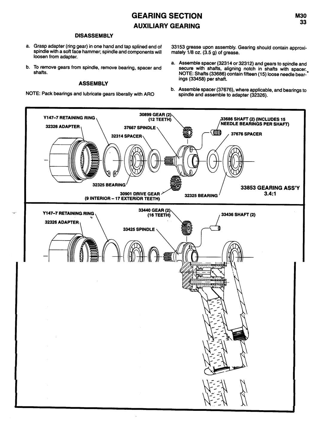
DISASSEMBLY
33
a.Grasp adapter (ring gear) in one hand and tap splined end of spindle with a soft face hammer; spindle and components will loosen from adapter.
b.To remove gears from spindle, remove bearing, spacer and shafts.
ASSEMBLY
NOTE: Pack bearings and lubricate gears liberally with ARO
33153 grease upon assembly. Gearing should contain approxi- mately 118oz. (3.5 g) of grease.
a.Assemble spacer (32314 or 32312) and gears to spindle and secure with shafts, aligning notch in shafts with spacer. NOTE: Shafts (33686) contain fifteen (15) loose needle
b.Assemble spacer (37676), where applicable, and bearings to spindle and assemble to adapter (32326).
| 3666 SHAFT (2) (INCLUDES 16 | |
32326 ADAPTER | 37667 SPINDLE |
|
| 32314 SPACER | 37676 SPACER |
32326 BEARING |
| 33853 GEARING ASS’Y |
|
| |
30901 DPIVE GEAR | 32325 BEARING | 3.4:1 |
(9 INTERIOR - 17 EXTERIOR TEETH) |
|
32326 ADAPTER
33425 SPINDLE
32325 BEARING |
|
| 33837 GEARING ASS’Y |
32312 SPACER | 32325 | BEARING | 5.56:1 |
|
|
9