DRIVE SECTION | M30 |
ADJUSTABLE CLUTCH | 33 |
| |
CLUTCH ADJUSTMENT | ASSEMBLY |
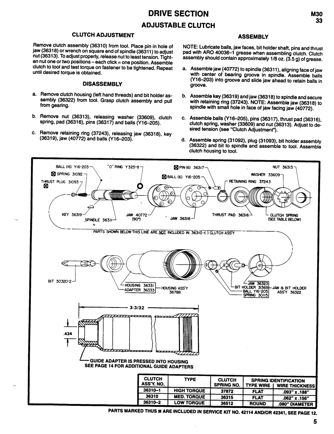
Remove clutch assembly (36310) from tool. Place pin in hole of jaw (36318) or wrench on square end of spindle (36311) to adjust nut (36313). To adjust properly, release nut to least tension. Tight- en nut one or two positions
DISASSEMBLY
a.Remove clutch housing (left hand threads) and bit holder as- sembly (36322) from tool. Grasp clutch assembly and pull from gearing.
b.Remove nut (36313) releasing washer (33609) clutch spring, pad (36316) pins (36317) and balls
c.Remove retaining ring (37243) releasing jaw (36318) key (36319) jaw (40772) and balls (Y
NOTE: Lubricate balls, jaw faces, bit holder shaft, pins and thrust pad with ARO
a.Assemble jaw (40772) to spindle (36311) aligning face of jaw with center of bearing groove in spindle. Assemble balls
b.Assemble key (36319) and jaw (36318) to spindle and secure with retaining ring (37243). NOTE: Assemble jaw (36318) to spindle with small hole in face of jaw facing jaw (40772).
c.Assemble balls
d.Assemble spring (31092) plug (31093) bit holder assembly (36322) and bit to spindle and assemble to tool. Assemble clutch housing to tool.
BALL | (16) | Y | “O” RING Y | @PIN | (6) 36317 | NUT 36313 |
SPRING | 31092, | 7 | q BALL (6) | WASHER 336091 | ||
THRUST PLUG | 310933 |
|
| RETAINING | RING 37243 | |
|
|
|
| |||
BIT
JAW 8 BIT HOLDER
ASS’Y 36322
/GUIDEADAPTERIS PRESSEDINTO HOUSING SEE PAGE 14 FOR ADDlTlONAL GUIDE ADAPTERS
CLUTCH | TYPE | CLUTCH | SPRING IDENTIFICATION | ||
ASS’Y. NO. |
| SPRING NO. | TYPE WIRE | WIRE THICKNESS | |
HIGH TORQUE | 37872 | FLAT | .093” | x .188” | |
38310 | MED. TORQUE | 36315 | FLAT | .062” | x .156” |
3831 | LOW TORQUE | 38512 | ROUND | .080” DIAMETER | |
PARTS MARKEDTHUS q ARE INCLUDED IN SERVICE KIT NO. 42114 AND/OR 42341, SEE PAGE 12.
5