MODEL IDENTIFICATION
MODELS WITH
NOTE: GENERAL PURPOSE WRENCH 37167 FURNISHED WITH
DISASSEMBLY AND ASSEMBLY OF TOOLS
Disconnect air supply from tool or shut off air supply and exhaust (drain) line of compressed air before performing maintenance or service to tool.
Before starting to disassemble or assemble this tool (any part or completely), be sure to read “Inspection,Maintenance and Instal- lation” section.
To minimize the possibility of parts damage and for convenience the steps for disassembly or assembly listed on the following pages are recommended.
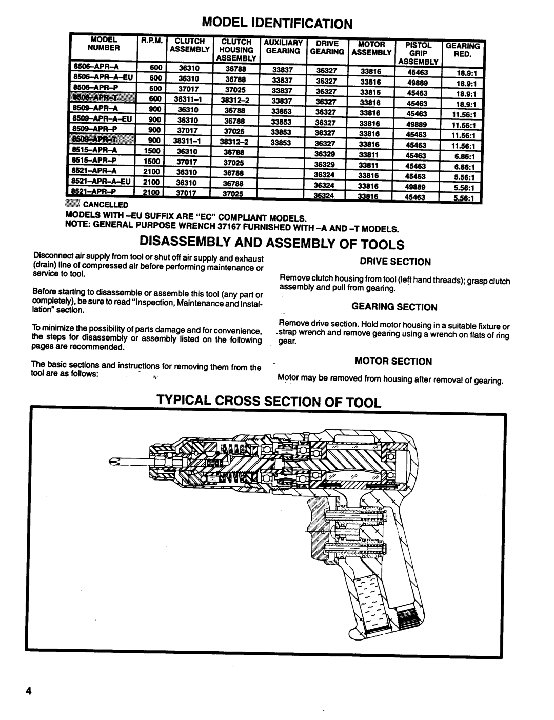
DRIVE SECTION
Remove clutch housing from tool (left hand threads); grasp clutch assembly and pull from gearing.
GEARING SECTION
Remove drive section. Hold motor housing in a suitable fixture or
strap wrench and remove gearing using a wrench on flats of ring gear.
The basic sections and instructions for removing them from the tool are as follows:
MOTOR SECTION
Motor may be removed from housing after removal of gearing.
TYPICAL CROSS SECTION OF TOOL
4