Quick Start
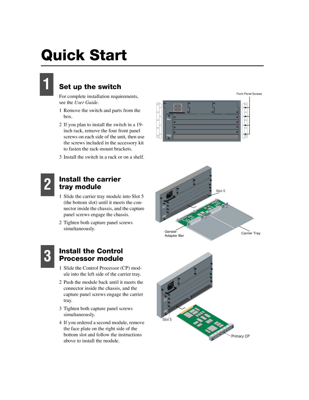
1 Set up the switch
For complete installation requirements, see the User Guide.
1Remove the switch and parts from the box.
2If you plan to install the switch in a 19- inch rack, remove the four front panel screws on each side of the unit, then use the screws included in the accessory kit to fasten the
3Install the switch in a rack or on a shelf.
Front Panel Screws
Install the carrier
2 tray module
1Slide the carrier tray module into Slot 5 (the bottom slot) until it meets the con- nector inside the chassis, and the capture panel screws engage the chassis.
2Tighten both capture panel screws simultaneously.
Install the Control
3 Processor module
1Slide the Control Processor (CP) mod- ule into the left side of the carrier tray.
2Push the module back until it meets the connector inside the chassis, and the capture panel screws engage the carrier tray.
3Tighten both capture panel screws simultaneously.
4If you ordered a second module, remove the face plate on the right side of the bottom slot and follow the instructions above to install the module.
Slot 5
Gender | Carrier Tray | |
Adapter Bar | ||
|
Slot 5
![]() Primary CP
Primary CP