Getting Started
Note: Please consider the thermal requirements of your Mobile Pentium II processor and ensure that the proper thermal management solution is in place.
2.2.2Emulator/Logic Analyzer
Connect the 30-pin cable from the emulator or logic analyzer to the debug port connector on the BX400ii Interposer Board. If you have a debug port designed into your system, only the debug port on the BX400ii Interposer Board will function. The port on the system board will not function with the BX400ii in place.
Connect the probe from the Mobile Pentium II processor logic analyzer to the 190-pin connector. Contact your logic analyzer vendor for specific details. A list of some third-party vendors is available in Table 2 on page 5.
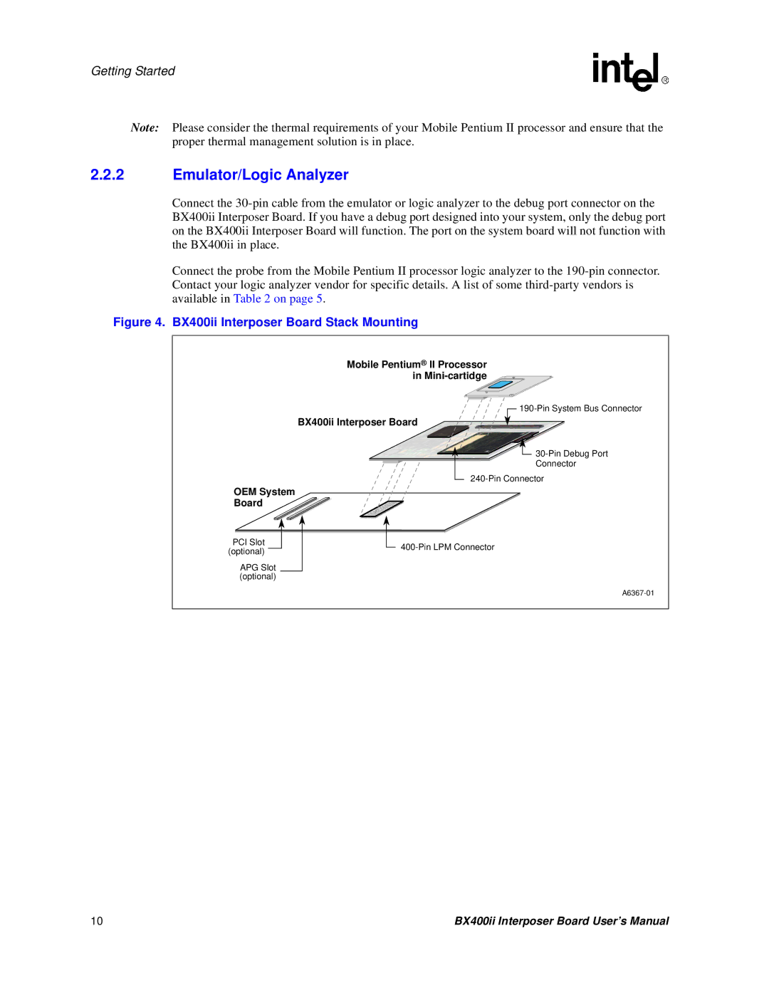
Figure 4. BX400ii Interposer Board Stack Mounting
Mobile Pentium® II Processor
in Mini-cartidge
190-Pin System Bus Connector
BX400ii Interposer Board
 30-Pin Debug Port
Connector
240-Pin Connector
OEM System
Board
PCI Slot (optional)
APG Slot (optional)
400-Pin LPM Connector
A6367-01
10 | BX400ii Interposer Board User’s Manual |