Manuals
/
Intel
/
Computer Equipment
/
Computer Hardware
Intel
BX400II
user manual
BX400ii Board Layout Drawing
Models:
BX400II
1
13
14
14
Download
14 pages
51.44 Kb
7
8
9
10
11
12
13
14
Install
Connector Definitions
Page 13
Image 13
Hardware Reference
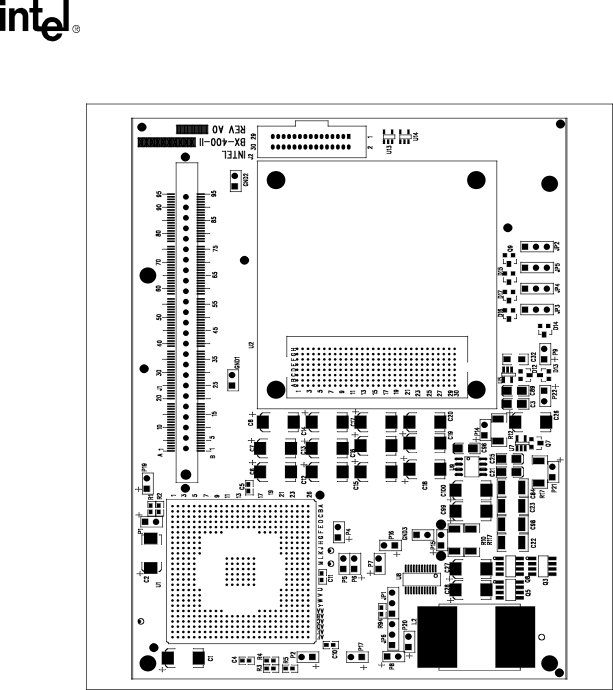
Figure 5. BX400ii Board Layout Drawing
BX400ii Interposer Board User’s Manual
13
Page 12
Page 14
Page 13
Image 13
Page 12
Page 14
Contents
User’s Manual
BX400ii Interposer Board
User’s Manual
Contents
Page
Key Terms
Introduction
Related Documents
BX400ii Interposer Board Features
Top View of BX400ii Interposer Board Assembly
Side View
BX400ii Interposer Board Dimensions
Important Static Electricity Precautions
Installation
Getting Started
Unpacking Instructions
BX400ii Interposer Board Stack Mounting
Emulator/Logic Analyzer
Jumper Settings
Connector Definitions
Voltage Regulator Settings
Hardware Reference
Test Points
Power Measurement Header Descriptions
BX400ii Board Layout Drawing
Top
Page
Image
Contents