Introduction
1.5BX400ii Interposer Board Dimensions
This section provides the physical dimensions for the BX400ii Interposer Board.
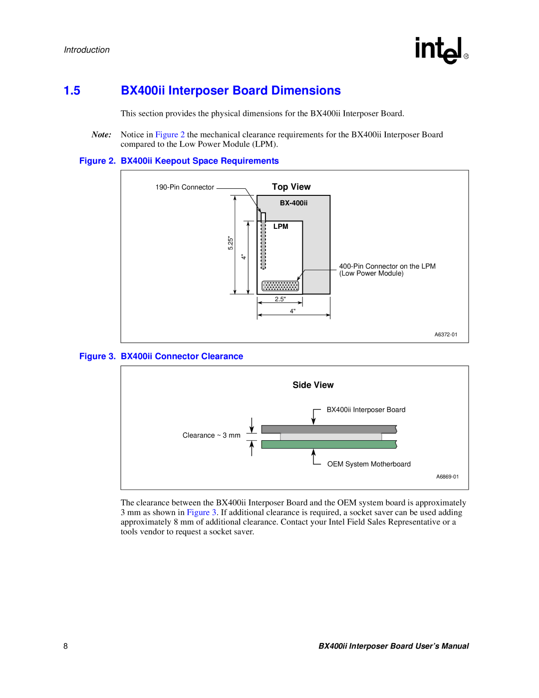
Note: Notice in Figure 2 the mechanical clearance requirements for the BX400ii Interposer Board compared to the Low Power Module (LPM).
Figure 2. BX400ii Keepout Space Requirements
5.25" 4"
Top View
LPM |
(Low Power Module) |
2.5" |
4" |
Figure 3. BX400ii Connector Clearance
Side View
BX400ii Interposer Board
Clearance ~ 3 mm
OEM System Motherboard
The clearance between the BX400ii Interposer Board and the OEM system board is approximately 3 mm as shown in Figure 3. If additional clearance is required, a socket saver can be used adding approximately 8 mm of additional clearance. Contact your Intel Field Sales Representative or a tools vendor to request a socket saver.
8 | BX400ii Interposer Board User’s Manual |
