Rev. A.3, 5/00 | Page- 5 |
2.4 GENERAL INSTALLATION ON INSWINGING DOOR WITH Z BRACKET
In cases where the Magnalock must be mounted on the inswinging side of the door to protect it from physical assault, the magnet body is mounted flush on the wall above the door frame and a "Z" bracket is affixed to the door which positions the strike in front of the Magnet (part #
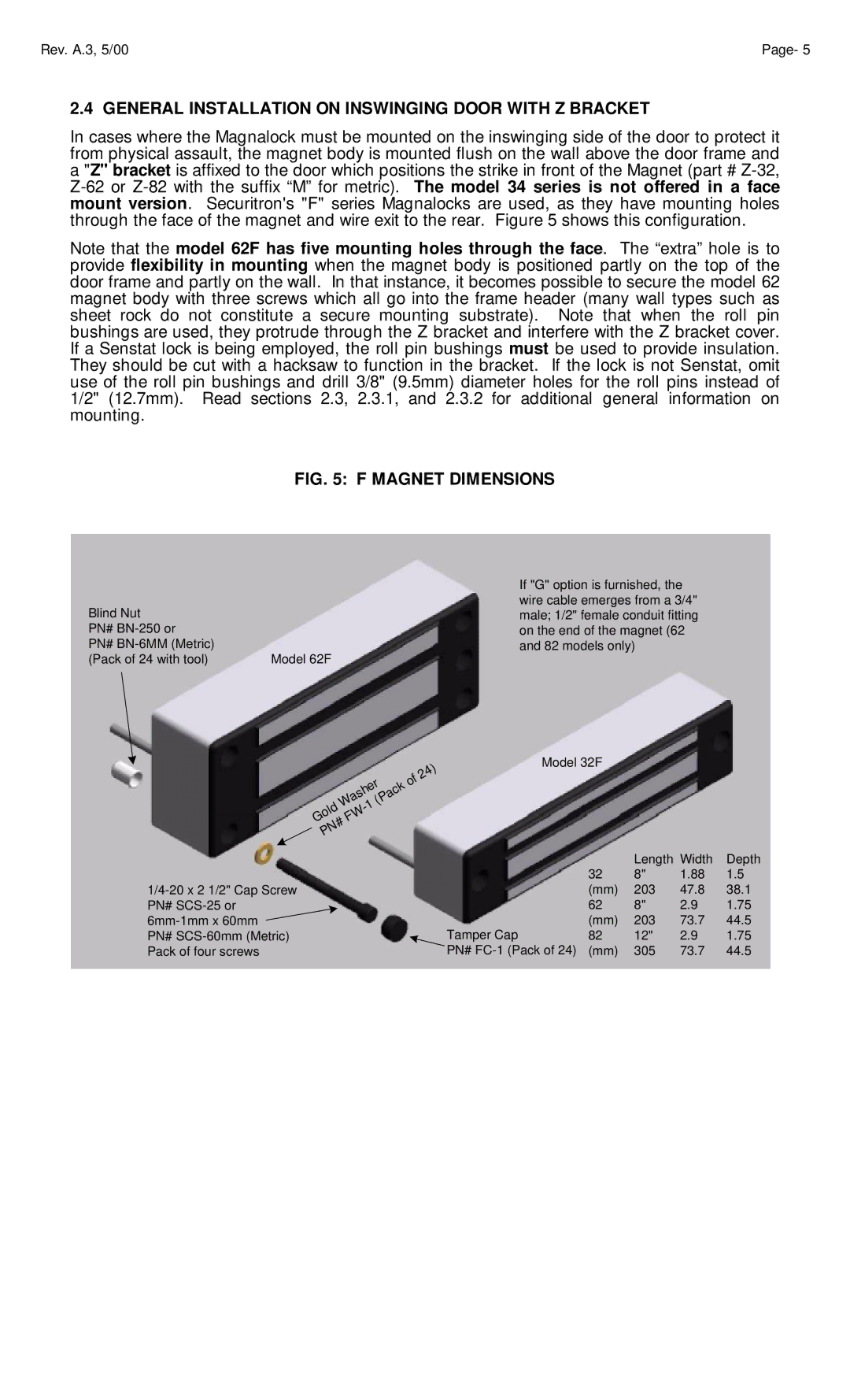
Note that the model 62F has five mounting holes through the face. The “extra” hole is to provide flexibility in mounting when the magnet body is positioned partly on the top of the door frame and partly on the wall. In that instance, it becomes possible to secure the model 62 magnet body with three screws which all go into the frame header (many wall types such as sheet rock do not constitute a secure mounting substrate). Note that when the roll pin bushings are used, they protrude through the Z bracket and interfere with the Z bracket cover. If a Senstat lock is being employed, the roll pin bushings must be used to provide insulation. They should be cut with a hacksaw to function in the bracket. If the lock is not Senstat, omit use of the roll pin bushings and drill 3/8" (9.5mm) diameter holes for the roll pins instead of 1/2" (12.7mm). Read sections 2.3, 2.3.1, and 2.3.2 for additional general information on mounting.
FIG. 5: F MAGNET DIMENSIONS
Blind Nut |
|
PN# |
|
PN# | Model 62F |
(Pack of 24 with tool) |
If "G" option is furnished, the wire cable emerges from a 3/4" male; 1/2" female conduit fitting on the end of the magnet (62 and 82 models only)
|
|
|
|
|
|
|
|
|
|
|
| ) |
|
|
|
|
|
|
|
|
|
|
| 4 | |
|
|
|
|
|
|
|
|
|
| 2 |
| |
|
|
|
|
| r |
|
|
| f |
|
| |
|
|
|
|
|
|
| o |
|
| |||
|
|
|
| e |
| k |
|
|
| |||
|
|
|
| h |
|
|
| c |
|
|
|
|
|
|
| s |
|
| a |
|
|
|
| ||
|
|
| a |
|
| P |
|
|
|
|
| |
|
| W |
| ( |
|
|
|
|
|
| ||
|
| 1 |
|
|
|
|
|
|
| |||
| d |
| - |
|
|
|
|
|
|
|
| |
| l |
| W |
|
|
|
|
|
|
|
| |
o |
|
|
|
|
|
|
|
|
| |||
G |
|
| F |
|
|
|
|
|
|
|
|
|
|
| # |
|
|
|
|
|
|
|
|
| |
| N |
|
|
|
|
|
|
|
|
|
| |
P |
|
|
|
|
|
|
|
|
|
|
| |
Model 32F
|
|
| Length Width | Depth | |
|
| 32 | 8" | 1.88 | 1.5 |
| (mm) | 203 | 47.8 | 38.1 | |
PN# |
| 62 | 8" | 2.9 | 1.75 |
Tamper Cap | (mm) | 203 | 73.7 | 44.5 | |
PN# | 82 | 12" | 2.9 | 1.75 | |
Pack of four screws | PN# | (mm) | 305 | 73.7 | 44.5 |
