Rev. A.3, 5/00 | Page- 7 |
method is to space the magnet down so as to clear the blade stop. This generally requires 1/2” of spacing (12.7mm) and Securitron offers brackets of the appropriate width with
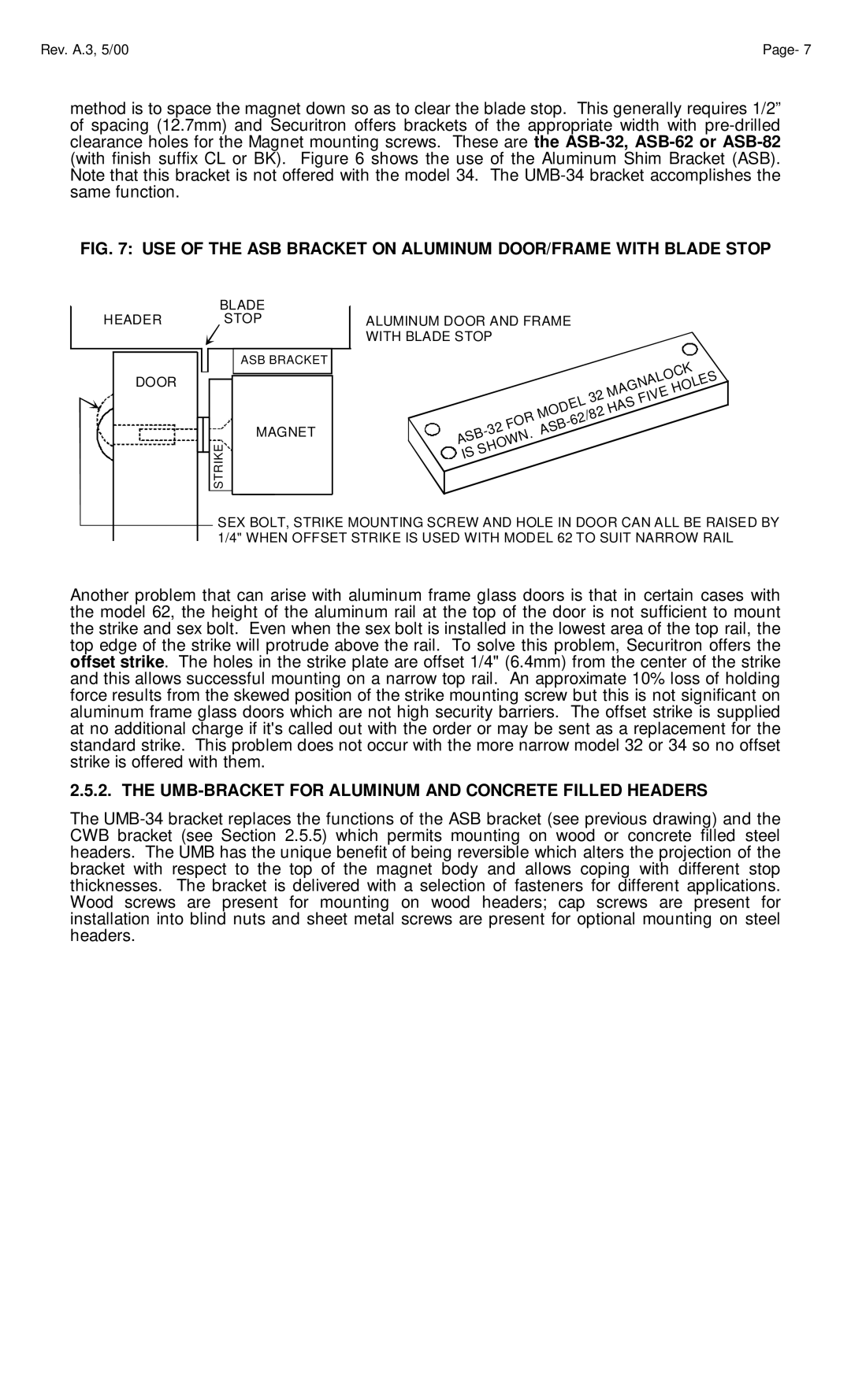
FIG. 7: USE OF THE ASB BRACKET ON ALUMINUM DOOR/FRAME WITH BLADE STOP
HEADER
DOOR
BLADE
STOP
ASB BRACKET
MAGNET
STRIKE
ALUMINUM DOOR AND FRAME
WITH BLADE STOP
|
|
|
|
|
|
|
|
|
|
|
|
|
|
|
|
|
|
|
|
|
| K |
|
| |
|
|
|
|
|
|
|
|
|
|
|
|
|
|
|
|
|
|
|
|
| C |
|
|
| |
|
|
|
|
|
|
|
|
|
|
|
|
|
|
|
|
|
|
|
| O |
|
|
| S | |
|
|
|
|
|
|
|
|
|
|
|
|
|
|
|
|
|
|
| L |
|
|
|
| ||
|
|
|
|
|
|
|
|
|
|
|
|
|
|
|
|
| A |
|
|
|
| E | |||
|
|
|
|
|
|
|
|
|
|
|
|
|
|
|
| N |
|
|
|
| L |
| |||
|
|
|
|
|
|
|
|
|
|
|
|
|
|
| G |
|
|
|
|
| O |
|
| ||
|
|
|
|
|
|
|
|
|
|
|
|
|
| A |
|
|
|
| E | H |
|
|
| ||
|
|
|
|
|
|
|
|
|
|
|
|
|
| M |
|
|
|
|
|
|
|
|
|
| |
|
|
|
|
|
|
|
|
|
|
|
|
| 2 |
|
|
|
| V |
|
|
|
|
| ||
|
|
|
|
|
|
|
|
|
|
|
|
|
|
|
| I |
|
|
|
|
|
|
| ||
|
|
|
|
|
|
|
|
|
|
| L3 |
| S | F |
|
|
|
|
|
|
|
| |||
|
|
|
|
|
|
|
|
|
| E |
|
|
|
|
|
|
|
|
|
|
|
|
| ||
|
|
|
|
|
|
|
|
| D |
|
|
| A |
|
|
|
|
|
|
|
|
|
| ||
|
|
|
|
|
|
|
|
|
|
|
| H |
|
|
|
|
|
|
|
|
|
|
| ||
|
|
|
|
|
|
|
| O |
|
|
| 2 |
|
|
|
|
|
|
|
|
|
|
|
| |
|
|
|
|
|
|
|
| M |
|
|
|
|
|
|
|
|
|
|
|
|
|
|
|
| |
|
|
|
|
|
|
| R |
|
|
|
| /8 |
|
|
|
|
|
|
|
|
|
|
|
| |
|
|
|
|
|
|
|
|
|
| 2 |
|
|
|
|
|
|
|
|
|
|
|
|
| ||
|
|
|
|
| O |
|
|
|
|
|
|
|
|
|
|
|
|
|
|
|
| ||||
|
|
| 2 | F |
|
|
| B |
|
|
|
|
|
|
|
|
|
|
|
|
|
|
| ||
|
|
|
|
|
|
| S |
|
|
|
|
|
|
|
|
|
|
|
|
|
|
|
| ||
|
|
|
|
| . | A |
|
|
|
|
|
|
|
|
|
|
|
|
|
|
|
|
| ||
| B |
|
|
|
|
|
|
|
|
|
|
|
|
|
|
|
|
|
|
|
|
|
| ||
S |
|
|
|
| N |
|
|
|
|
|
|
|
|
|
|
|
|
|
|
|
|
|
| ||
A |
|
|
| W |
|
|
|
|
|
|
|
|
|
|
|
|
|
|
|
|
|
|
| ||
|
|
| O |
|
|
|
|
|
|
|
|
|
|
|
|
|
|
|
|
|
|
|
|
| |
|
| H |
|
|
|
|
|
|
|
|
|
|
|
|
|
|
|
|
|
|
|
|
|
| |
SS |
|
|
|
|
|
|
|
|
|
|
|
|
|
|
|
|
|
|
|
|
|
|
| ||
I |
|
|
|
|
|
|
|
|
|
|
|
|
|
|
|
|
|
|
|
|
|
|
|
|
|
SEX BOLT, STRIKE MOUNTING SCREW AND HOLE IN DOOR CAN ALL BE RAISED BY 1/4" WHEN OFFSET STRIKE IS USED WITH MODEL 62 TO SUIT NARROW RAIL
Another problem that can arise with aluminum frame glass doors is that in certain cases with the model 62, the height of the aluminum rail at the top of the door is not sufficient to mount the strike and sex bolt. Even when the sex bolt is installed in the lowest area of the top rail, the top edge of the strike will protrude above the rail. To solve this problem, Securitron offers the offset strike. The holes in the strike plate are offset 1/4" (6.4mm) from the center of the strike and this allows successful mounting on a narrow top rail. An approximate 10% loss of holding force results from the skewed position of the strike mounting screw but this is not significant on aluminum frame glass doors which are not high security barriers. The offset strike is supplied at no additional charge if it's called out with the order or may be sent as a replacement for the standard strike. This problem does not occur with the more narrow model 32 or 34 so no offset strike is offered with them.
2.5.2. THE UMB-BRACKET FOR ALUMINUM AND CONCRETE FILLED HEADERS
The