Rev. A.3, 5/00 | Page- 2 |
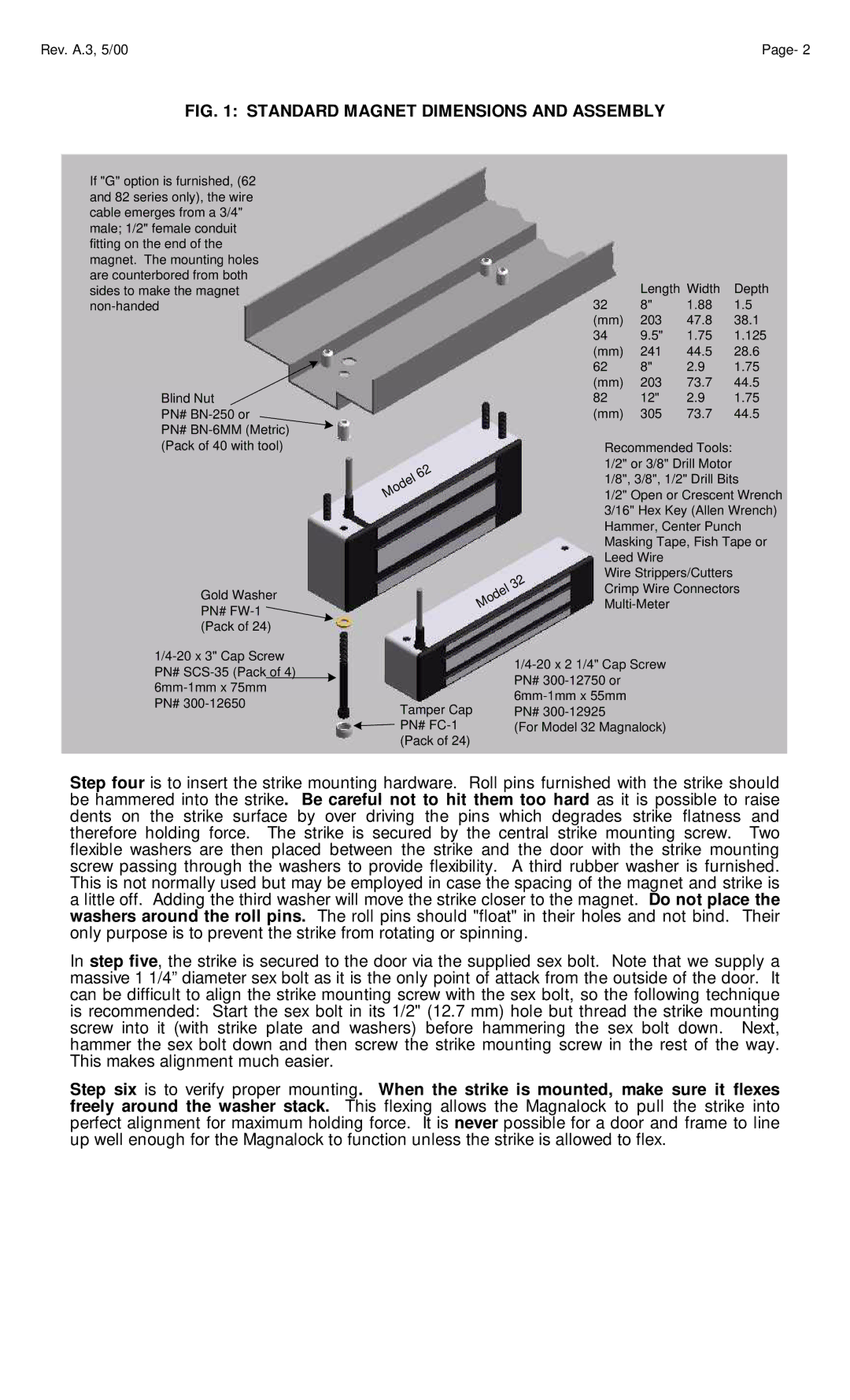
FIG. 1: STANDARD MAGNET DIMENSIONS AND ASSEMBLY
If "G" option is furnished, (62 and 82 series only), the wire cable emerges from a 3/4" male; 1/2" female conduit fitting on the end of the magnet. The mounting holes are counterbored from both sides to make the magnet
Blind Nut
PN#
PN#
Gold Washer PN# ![]() (Pack of 24)
(Pack of 24)
|
|
|
| 2 |
|
|
| 6 | |
|
|
| l |
|
|
| e |
| |
| d |
|
| |
o |
|
|
| |
M |
|
|
|
|
|
|
|
| 2 |
|
|
| 3 | |
|
|
| l |
|
|
| e |
| |
| d |
|
| |
o |
|
|
| |
M |
|
|
|
|
| Length | Width | Depth |
32 | 8" | 1.88 | 1.5 |
(mm) | 203 | 47.8 | 38.1 |
34 | 9.5" | 1.75 | 1.125 |
(mm) | 241 | 44.5 | 28.6 |
62 | 8" | 2.9 | 1.75 |
(mm) | 203 | 73.7 | 44.5 |
82 | 12" | 2.9 | 1.75 |
(mm) | 305 | 73.7 | 44.5 |
Recommended Tools: 1/2" or 3/8" Drill Motor 1/8", 3/8", 1/2" Drill Bits
1/2" Open or Crescent Wrench 3/16" Hex Key (Allen Wrench) Hammer, Center Punch Masking Tape, Fish Tape or Leed Wire
Wire Strippers/Cutters
Crimp Wire Connectors
| |
| PN# |
Tamper Cap | |
PN# | |
PN# | (For Model 32 Magnalock) |
(Pack of 24) |
|
Step four is to insert the strike mounting hardware. Roll pins furnished with the strike should be hammered into the strike. Be careful not to hit them too hard as it is possible to raise dents on the strike surface by over driving the pins which degrades strike flatness and therefore holding force. The strike is secured by the central strike mounting screw. Two flexible washers are then placed between the strike and the door with the strike mounting screw passing through the washers to provide flexibility. A third rubber washer is furnished. This is not normally used but may be employed in case the spacing of the magnet and strike is a little off. Adding the third washer will move the strike closer to the magnet. Do not place the washers around the roll pins. The roll pins should "float" in their holes and not bind. Their only purpose is to prevent the strike from rotating or spinning.
In step five, the strike is secured to the door via the supplied sex bolt. Note that we supply a massive 1 1/4” diameter sex bolt as it is the only point of attack from the outside of the door. It can be difficult to align the strike mounting screw with the sex bolt, so the following technique is recommended: Start the sex bolt in its 1/2" (12.7 mm) hole but thread the strike mounting screw into it (with strike plate and washers) before hammering the sex bolt down. Next, hammer the sex bolt down and then screw the strike mounting screw in the rest of the way. This makes alignment much easier.
Step six is to verify proper mounting. When the strike is mounted, make sure it flexes freely around the washer stack. This flexing allows the Magnalock to pull the strike into perfect alignment for maximum holding force. It is never possible for a door and frame to line up well enough for the Magnalock to function unless the strike is allowed to flex.