Rev. A.3, 5/00 | Page- 15 |
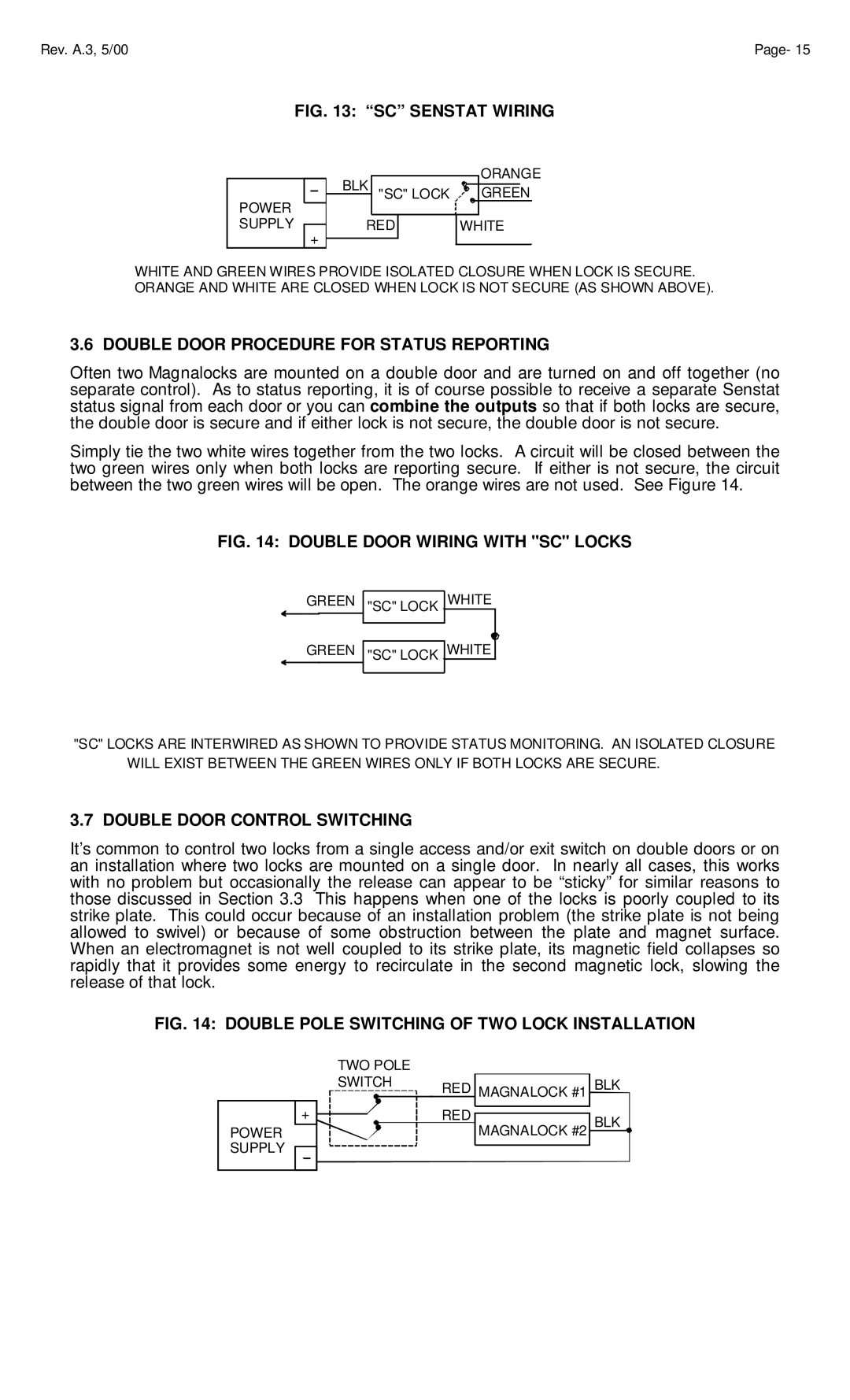
FIG. 13: “SC” SENSTAT WIRING
ORANGE
BLK "SC" LOCK ![]()
![]()
![]() GREEN
GREEN
POWER |
|
|
SUPPLY | RED | WHITE |
| + |
|
WHITE AND GREEN WIRES PROVIDE ISOLATED CLOSURE WHEN LOCK IS SECURE. ORANGE AND WHITE ARE CLOSED WHEN LOCK IS NOT SECURE (AS SHOWN ABOVE).
3.6 DOUBLE DOOR PROCEDURE FOR STATUS REPORTING
Often two Magnalocks are mounted on a double door and are turned on and off together (no separate control). As to status reporting, it is of course possible to receive a separate Senstat status signal from each door or you can combine the outputs so that if both locks are secure, the double door is secure and if either lock is not secure, the double door is not secure.
Simply tie the two white wires together from the two locks. A circuit will be closed between the two green wires only when both locks are reporting secure. If either is not secure, the circuit between the two green wires will be open. The orange wires are not used. See Figure 14.
FIG. 14: DOUBLE DOOR WIRING WITH "SC" LOCKS
GREEN "SC" LOCK WHITE
GREEN "SC" LOCK WHITE
"SC" LOCKS ARE INTERWIRED AS SHOWN TO PROVIDE STATUS MONITORING. AN ISOLATED CLOSURE WILL EXIST BETWEEN THE GREEN WIRES ONLY IF BOTH LOCKS ARE SECURE.
3.7 DOUBLE DOOR CONTROL SWITCHING
It’s common to control two locks from a single access and/or exit switch on double doors or on an installation where two locks are mounted on a single door. In nearly all cases, this works with no problem but occasionally the release can appear to be “sticky” for similar reasons to those discussed in Section 3.3 This happens when one of the locks is poorly coupled to its strike plate. This could occur because of an installation problem (the strike plate is not being allowed to swivel) or because of some obstruction between the plate and magnet surface. When an electromagnet is not well coupled to its strike plate, its magnetic field collapses so rapidly that it provides some energy to recirculate in the second magnetic lock, slowing the release of that lock.
FIG. 14: DOUBLE POLE SWITCHING OF TWO LOCK INSTALLATION
|
|
| TWO POLE |
|
| ||||||||||||||
|
|
| SWITCH | RED MAGNALOCK #1 | BLK | ||||||||||||||
+ |
|
|
|
|
|
|
|
|
|
|
|
|
|
|
|
|
| RED | BLK |
|
|
|
|
|
|
|
|
|
|
|
|
|
|
|
|
| |||
|
|
|
|
|
|
|
|
|
|
|
|
|
|
|
|
| |||
|
|
|
|
|
|
|
|
|
|
|
|
|
|
|
|
| |||
|
|
|
|
|
|
|
|
|
|
|
|
|
|
|
|
| |||
|
|
|
|
|
|
|
|
|
|
|
|
|
|
|
|
| |||
|
|
|
|
|
|
|
|
|
|
|
|
|
|
|
|
| |||
POWER |
|
|
|
|
|
|
|
|
|
|
|
|
|
|
|
|
| MAGNALOCK #2 | |
|
|
|
|
|
|
|
|
|
|
|
|
|
|
|
|
| |||
|
|
|
|
|
|
|
|
|
|
|
|
|
|
|
|
| |||
|
|
|
|
|
|
|
|
|
|
|
|
|
|
|
|
|
| ||
SUPPLY