Rev. A.3, 5/00 | Page- 6 |
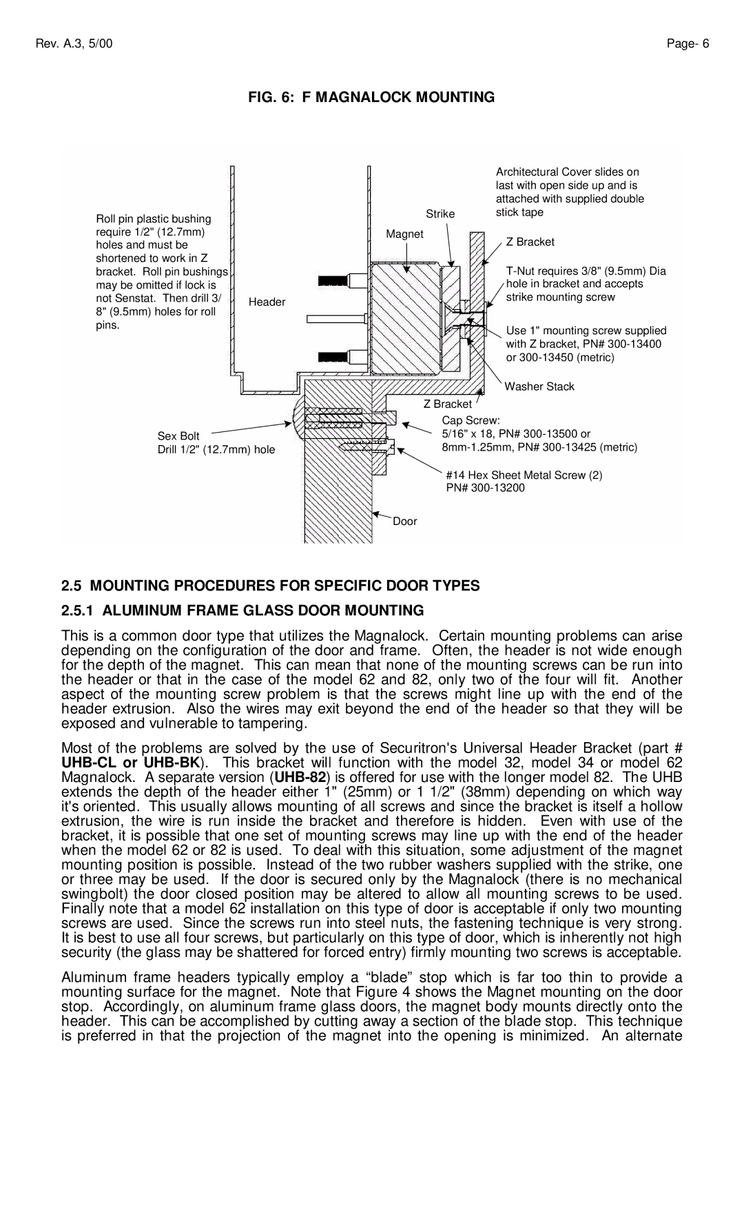
FIG. 6: F MAGNALOCK MOUNTING
Roll pin plastic bushing require 1/2" (12.7mm) holes and must be shortened to work in Z bracket. Roll pin bushings may be omitted if lock is
not Senstat. Then drill 3/ Header 8" (9.5mm) holes for roll
pins.
Sex Bolt
Drill 1/2" (12.7mm) hole
|
| Architectural Cover slides on |
|
| last with open side up and is |
|
| attached with supplied double |
| Strike | stick tape |
Magnet | Z Bracket | |
|
| |
|
| |
|
| |
|
| |
|
| hole in bracket and accepts |
|
| strike mounting screw |
|
| Use 1" mounting screw supplied |
|
| with Z bracket, PN# |
|
| or |
|
| Washer Stack |
| Z Bracket |
|
Cap Screw:
5/16" x 18, PN#
#14 Hex Sheet Metal Screw (2) PN#
![]() Door
Door
2.5MOUNTING PROCEDURES FOR SPECIFIC DOOR TYPES 2.5.1 ALUMINUM FRAME GLASS DOOR MOUNTING
This is a common door type that utilizes the Magnalock. Certain mounting problems can arise depending on the configuration of the door and frame. Often, the header is not wide enough for the depth of the magnet. This can mean that none of the mounting screws can be run into the header or that in the case of the model 62 and 82, only two of the four will fit. Another aspect of the mounting screw problem is that the screws might line up with the end of the header extrusion. Also the wires may exit beyond the end of the header so that they will be exposed and vulnerable to tampering.
Most of the problems are solved by the use of Securitron's Universal Header Bracket (part #
Aluminum frame headers typically employ a “blade” stop which is far too thin to provide a mounting surface for the magnet. Note that Figure 4 shows the Magnet mounting on the door stop. Accordingly, on aluminum frame glass doors, the magnet body mounts directly onto the header. This can be accomplished by cutting away a section of the blade stop. This technique is preferred in that the projection of the magnet into the opening is minimized. An alternate