Rev. A.3, 5/00 | Page- 12 |
In the case of very tall and large gates, a levering problem can exist. By this we mean that an intruder may be able to flex the gate enough to take up the slack in the strike mounting screw and then lever off the strike plate. If the installer or user determines that this may happen, a single Magnalock will not provide adequate security and two must be used, typically at the top and bottom of the gate.
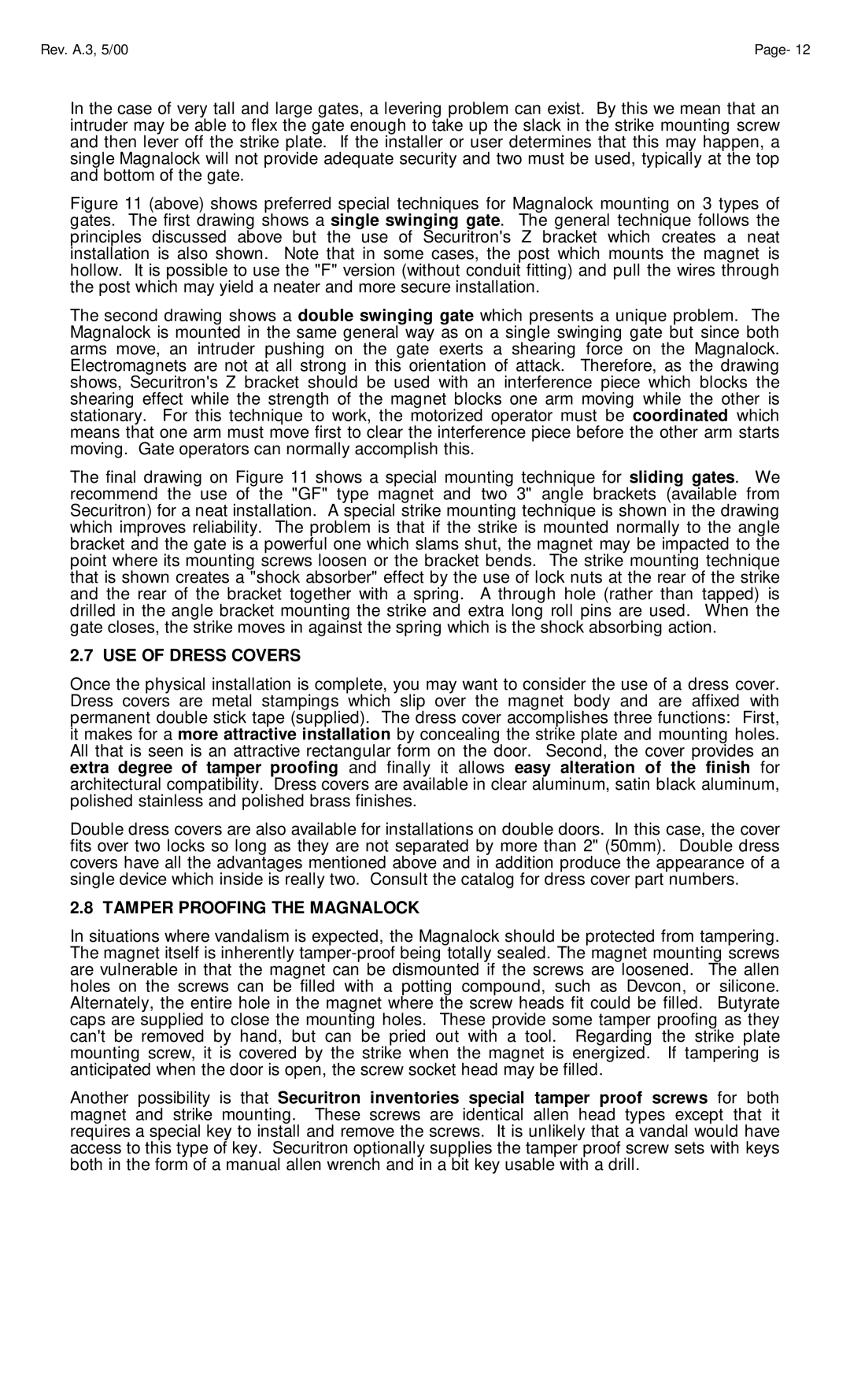
Figure 11 (above) shows preferred special techniques for Magnalock mounting on 3 types of gates. The first drawing shows a single swinging gate. The general technique follows the principles discussed above but the use of Securitron's Z bracket which creates a neat installation is also shown. Note that in some cases, the post which mounts the magnet is hollow. It is possible to use the "F" version (without conduit fitting) and pull the wires through the post which may yield a neater and more secure installation.
The second drawing shows a double swinging gate which presents a unique problem. The Magnalock is mounted in the same general way as on a single swinging gate but since both arms move, an intruder pushing on the gate exerts a shearing force on the Magnalock. Electromagnets are not at all strong in this orientation of attack. Therefore, as the drawing shows, Securitron's Z bracket should be used with an interference piece which blocks the shearing effect while the strength of the magnet blocks one arm moving while the other is stationary. For this technique to work, the motorized operator must be coordinated which means that one arm must move first to clear the interference piece before the other arm starts moving. Gate operators can normally accomplish this.
The final drawing on Figure 11 shows a special mounting technique for sliding gates. We recommend the use of the "GF" type magnet and two 3" angle brackets (available from Securitron) for a neat installation. A special strike mounting technique is shown in the drawing which improves reliability. The problem is that if the strike is mounted normally to the angle bracket and the gate is a powerful one which slams shut, the magnet may be impacted to the point where its mounting screws loosen or the bracket bends. The strike mounting technique that is shown creates a "shock absorber" effect by the use of lock nuts at the rear of the strike and the rear of the bracket together with a spring. A through hole (rather than tapped) is drilled in the angle bracket mounting the strike and extra long roll pins are used. When the gate closes, the strike moves in against the spring which is the shock absorbing action.
2.7 USE OF DRESS COVERS
Once the physical installation is complete, you may want to consider the use of a dress cover. Dress covers are metal stampings which slip over the magnet body and are affixed with permanent double stick tape (supplied). The dress cover accomplishes three functions: First, it makes for a more attractive installation by concealing the strike plate and mounting holes. All that is seen is an attractive rectangular form on the door. Second, the cover provides an extra degree of tamper proofing and finally it allows easy alteration of the finish for architectural compatibility. Dress covers are available in clear aluminum, satin black aluminum, polished stainless and polished brass finishes.
Double dress covers are also available for installations on double doors. In this case, the cover fits over two locks so long as they are not separated by more than 2" (50mm). Double dress covers have all the advantages mentioned above and in addition produce the appearance of a single device which inside is really two. Consult the catalog for dress cover part numbers.
2.8 TAMPER PROOFING THE MAGNALOCK
In situations where vandalism is expected, the Magnalock should be protected from tampering. The magnet itself is inherently
Another possibility is that Securitron inventories special tamper proof screws for both magnet and strike mounting. These screws are identical allen head types except that it requires a special key to install and remove the screws. It is unlikely that a vandal would have access to this type of key. Securitron optionally supplies the tamper proof screw sets with keys both in the form of a manual allen wrench and in a bit key usable with a drill.