Introduction
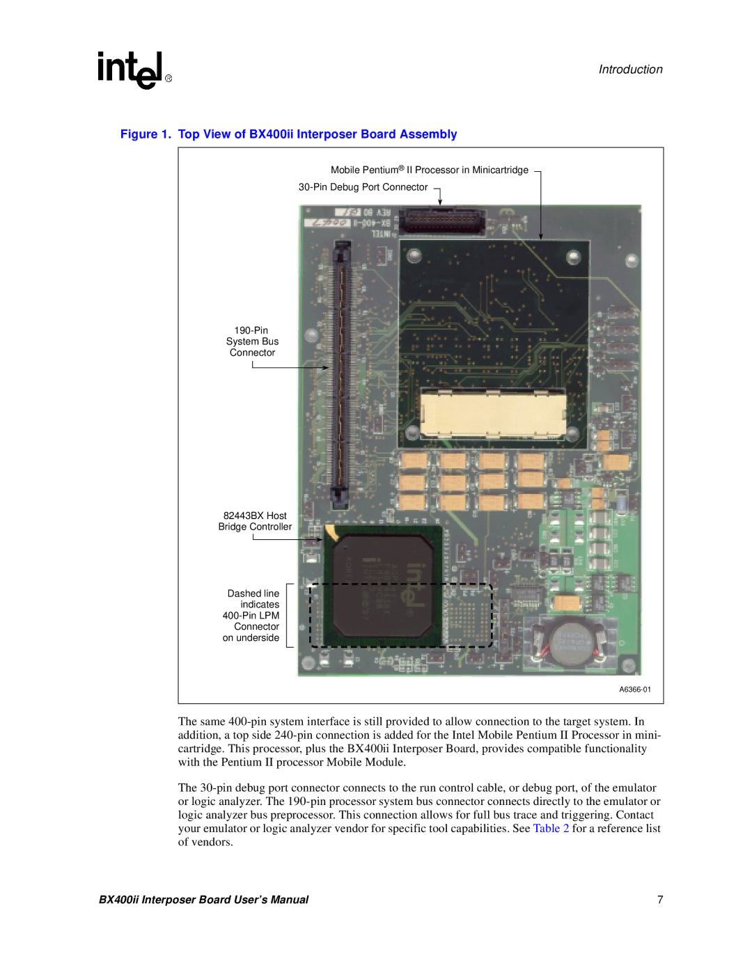
Figure 1. Top View of BX400ii Interposer Board Assembly
Mobile Pentium® II Processor in Minicartridge
30-Pin Debug Port Connector
190-Pin System Bus Connector
82443BX Host
Bridge Controller
Dashed line indicates
400-Pin LPM Connector on underside
A6366-01
The same 400-pin system interface is still provided to allow connection to the target system. In addition, a top side 240-pin connection is added for the Intel Mobile Pentium II Processor in mini- cartridge. This processor, plus the BX400ii Interposer Board, provides compatible functionality with the Pentium II processor Mobile Module.
The 30-pin debug port connector connects to the run control cable, or debug port, of the emulator or logic analyzer. The 190-pin processor system bus connector connects directly to the emulator or logic analyzer bus preprocessor. This connection allows for full bus trace and triggering. Contact your emulator or logic analyzer vendor for specific tool capabilities. See Table 2 for a reference list of vendors.
BX400ii Interposer Board User’s Manual | 7 |