Chapter 2 Switch Installation
Connecting to Power
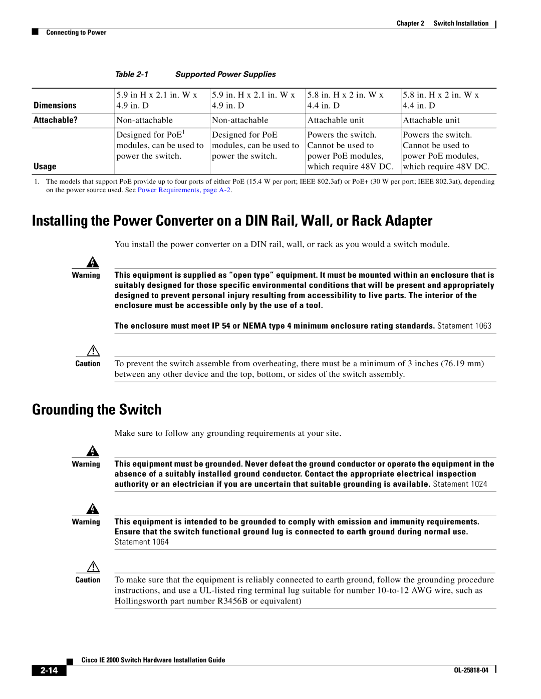
| Table | Supported Power Supplies |
|
| |
|
|
|
|
| |
| 5.9 in H x 2.1 in. W x | 5.9 in. H x 2.1 in. W x | 5.8 in. H x 2 in. W x | 5.8 in. H x 2 in. W x | |
Dimensions | 4.9 in. D |
| 4.9 in. D | 4.4 in. D | 4.4 in. D |
|
|
|
|
|
|
Attachable? |
| Attachable unit | Attachable unit | ||
|
|
|
|
| |
| Designed for PoE1 | Designed for PoE | Powers the switch. | Powers the switch. | |
| modules, can be used to | modules, can be used to | Cannot be used to | Cannot be used to | |
| power the switch. | power the switch. | power PoE modules, | power PoE modules, | |
Usage |
|
|
| which require 48V DC. | which require 48V DC. |
|
|
|
|
|
|
1.The models that support PoE provide up to four ports of either PoE (15.4 W per port; IEEE 802.3af) or PoE+ (30 W per port; IEEE 802.3at), depending on the power source used. See Power Requirements, page
Installing the Power Converter on a DIN Rail, Wall, or Rack Adapter
You install the power converter on a DIN rail, wall, or rack as you would a switch module.
Warning This equipment is supplied as “open type” equipment. It must be mounted within an enclosure that is suitably designed for those specific environmental conditions that will be present and appropriately designed to prevent personal injury resulting from accessibility to live parts. The interior of the enclosure must be accessible only by the use of a tool.
The enclosure must meet IP 54 or NEMA type 4 minimum enclosure rating standards. Statement 1063
Caution To prevent the switch assemble from overheating, there must be a minimum of 3 inches (76.19 mm) between any other device and the top, bottom, or sides of the switch assembly.
Grounding the Switch
Make sure to follow any grounding requirements at your site.
Warning This equipment must be grounded. Never defeat the ground conductor or operate the equipment in the absence of a suitably installed ground conductor. Contact the appropriate electrical inspection authority or an electrician if you are uncertain that suitable grounding is available. Statement 1024
Warning This equipment is intended to be grounded to comply with emission and immunity requirements. Ensure that the switch functional ground lug is connected to earth ground during normal use. Statement 1064
Caution To make sure that the equipment is reliably connected to earth ground, follow the grounding procedure instructions, and use a
| Cisco IE 2000 Switch Hardware Installation Guide |