Chapter 2 Switch Installation
Connecting to Power
Warning A readily accessible
Warning This product relies on the building’s installation for
Statement 1005
Warning Installation of the equipment must comply with local and national electrical codes. Statement 1074
Warning Before performing any of the following procedures, ensure that power is removed from the DC circuit. Statement 1003
Warning Only trained and qualified personnel should be allowed to install, replace, or service this equipment. Statement 1030
Caution For wire connections to the power and alarm connectors, you must use UL- and
To wire the switch to a DC power source, follow these steps:
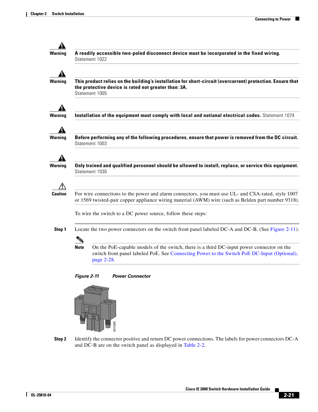
Step 1 Locate the two power connectors on the switch front panel labeled
Note On the
Figure 2-11 Power Connector
331209
Step 2 Identify the connector positive and return DC power connections. The labels for power connectors
|
| Cisco IE 2000 Switch Hardware Installation Guide |
|
| |
|
|
| |||
|
|
|
| ||
|
|
|
| ||