Cisco Systems IE20004TSB manual Alarm Port, Figure B-5 USB Type A-to-USB 5-Pin Mini-Type B Cable

Models: IE20004TSL IE200016TCB IE20004TSB

1 110
Download 110 pages 40.22 Kb
Page 93
Image 93

Appendix B Cable and Connectors

Connector Specifications

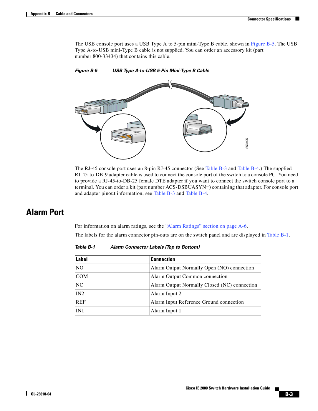
The USB console port uses a USB Type A to 5-pin mini-Type B cable, shown in Figure B-5. The USB Type A-to-USB mini-Type B cable is not supplied. You can order an accessory kit (part

number 800-33434) that contains this cable.

Figure B-5 USB Type A-to-USB 5-Pin Mini-Type B Cable

253405

The RJ-45 console port uses an 8-pin RJ-45 connector (See Table B-3and Table B-4.) The supplied RJ-45-to-DB-9 adapter cable is used to connect the console port of the switch to a console PC. You need to provide a RJ-45-to-DB-25 female DTE adapter if you want to connect the switch console port to a terminal. You can order a kit (part number ACS-DSBUASYN=) containing that adapter. For console port and adapter pinout information, see Table B-3and Table B-4.

Alarm Port

For information on alarm ratings, see the “Alarm Ratings” section on page A-6.

The labels for the alarm connector pin-outs are on the switch panel and are displayed in Table B-1.

Table B-1

Alarm Connector Labels (Top to Bottom)


Label


Connection


NO


Alarm Output Normally Open (NO) connection


COM


Alarm Output Common connection


NC


Alarm Output Normally Closed (NC) connection


IN2


Alarm Input 2


REF


Alarm Input Reference Ground connection


IN1


Alarm Input 1


Cisco IE 2000 Switch Hardware Installation Guide


OL-25818-04

B-3


Page 93
Image 93
Cisco Systems IE20004TSB, IE20004TSL, IE200016TCB manual Alarm Port, Figure B-5 USB Type A-to-USB 5-Pin Mini-Type B Cable