Chapter 2 Switch Installation
Installing the Switch
Caution To prevent the switch from overheating, ensure these minimum clearances:
–Top and bottom: 2.0 in. (50.8 mm)
–Exposed side (not connected to the module): 2.0 in. (50.8 mm)
–Front: 2.0 in. (50.8 mm)
Installing the Switch on a DIN Rail
The switch ships with a
You can install the switch as a standalone device on the DIN rail or with the expansion modules already connected. You must connect expansion modules to the switch before installing the switch on the DIN rail.
To attach the switch to a DIN rail, follow these steps:
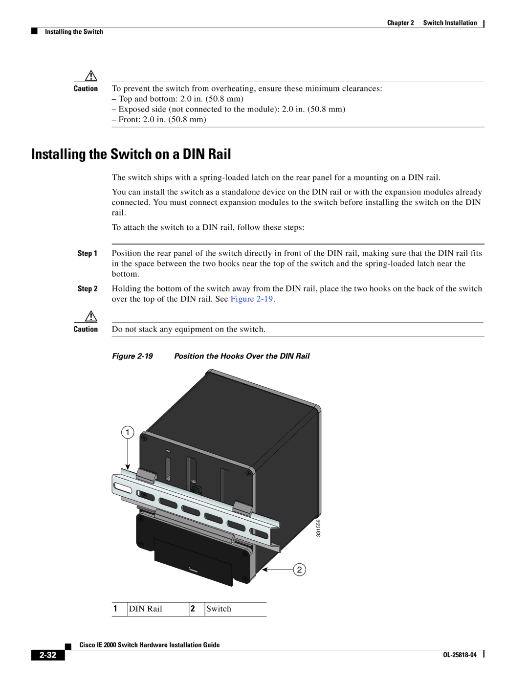
Step 1 Position the rear panel of the switch directly in front of the DIN rail, making sure that the DIN rail fits in the space between the two hooks near the top of the switch and the
Step 2 Holding the bottom of the switch away from the DIN rail, place the two hooks on the back of the switch over the top of the DIN rail. See Figure
Caution Do not stack any equipment on the switch.
Figure 2-19 Position the Hooks Over the DIN Rail
1
331556
2
1
DIN Rail
2
Switch
| Cisco IE 2000 Switch Hardware Installation Guide |