Chapter 2 Switch Installation
Connecting Alarm Circuits
Step 6 Repeat Step 2 through Step 5 to insert the input and output wires of one additional external alarm device into the alarm connector.
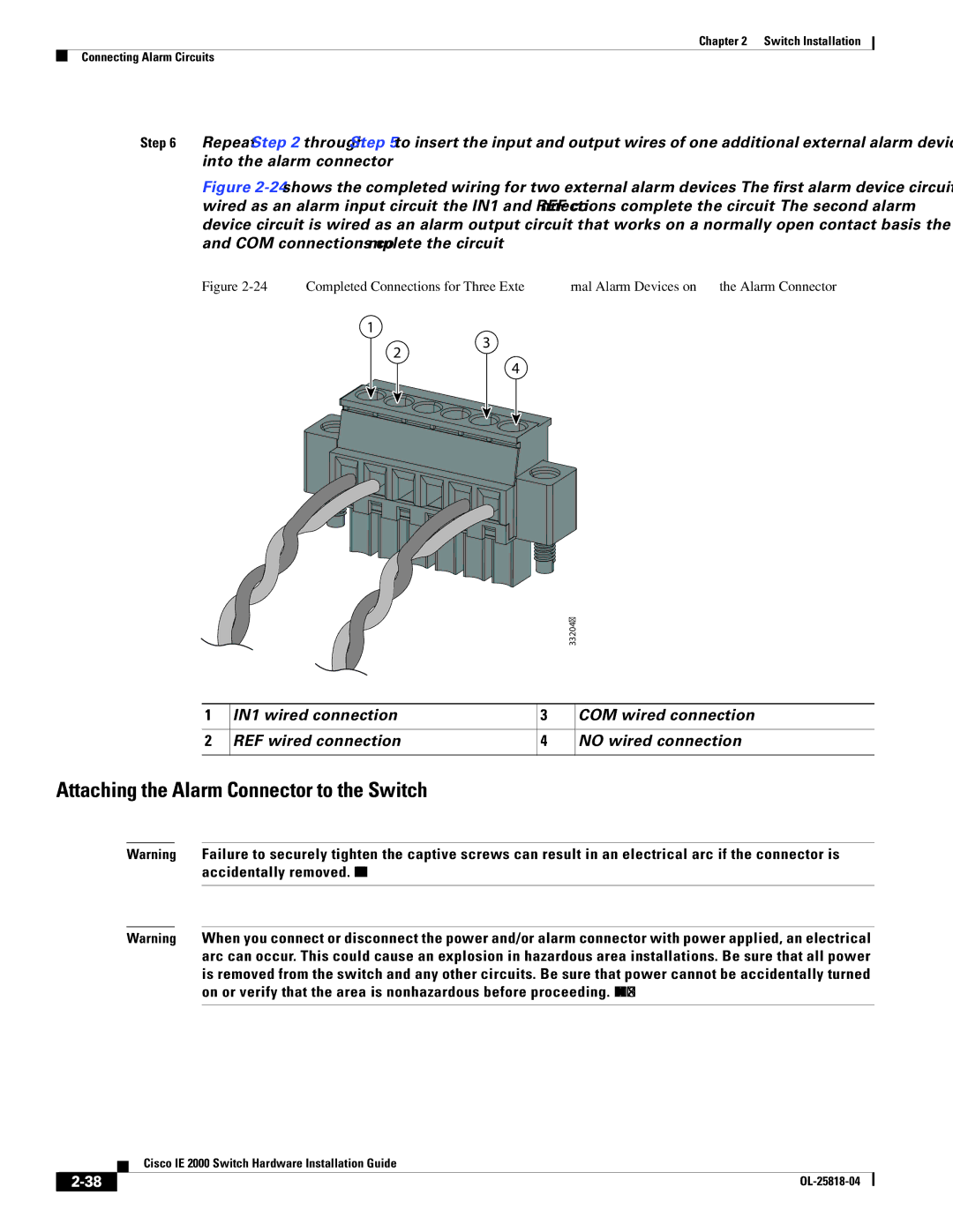
Figure 2-24 shows the completed wiring for two external alarm devices. The first alarm device circuit is wired as an alarm input circuit; the IN1 and REF connections complete the circuit. The second alarm device circuit is wired as an alarm output circuit that works on a normally open contact basis; the NO and COM connections complete the circuit.
Figure 2-24 Completed Connections for Three External Alarm Devices on the Alarm Connector
1
2
3
4
|
|
| 332047 |
1 | IN1 wired connection | 3 | COM wired connection |
2 | REF wired connection | 4 | NO wired connection |
Attaching the Alarm Connector to the Switch
Warning Failure to securely tighten the captive screws can result in an electrical arc if the connector is accidentally removed. Statement 397
Warning When you connect or disconnect the power and/or alarm connector with power applied, an electrical arc can occur. This could cause an explosion in hazardous area installations. Be sure that all power is removed from the switch and any other circuits. Be sure that power cannot be accidentally turned on or verify that the area is nonhazardous before proceeding. Statement 1058
| Cisco IE 2000 Switch Hardware Installation Guide |