Chapter 2 Switch Installation
Connecting to Power
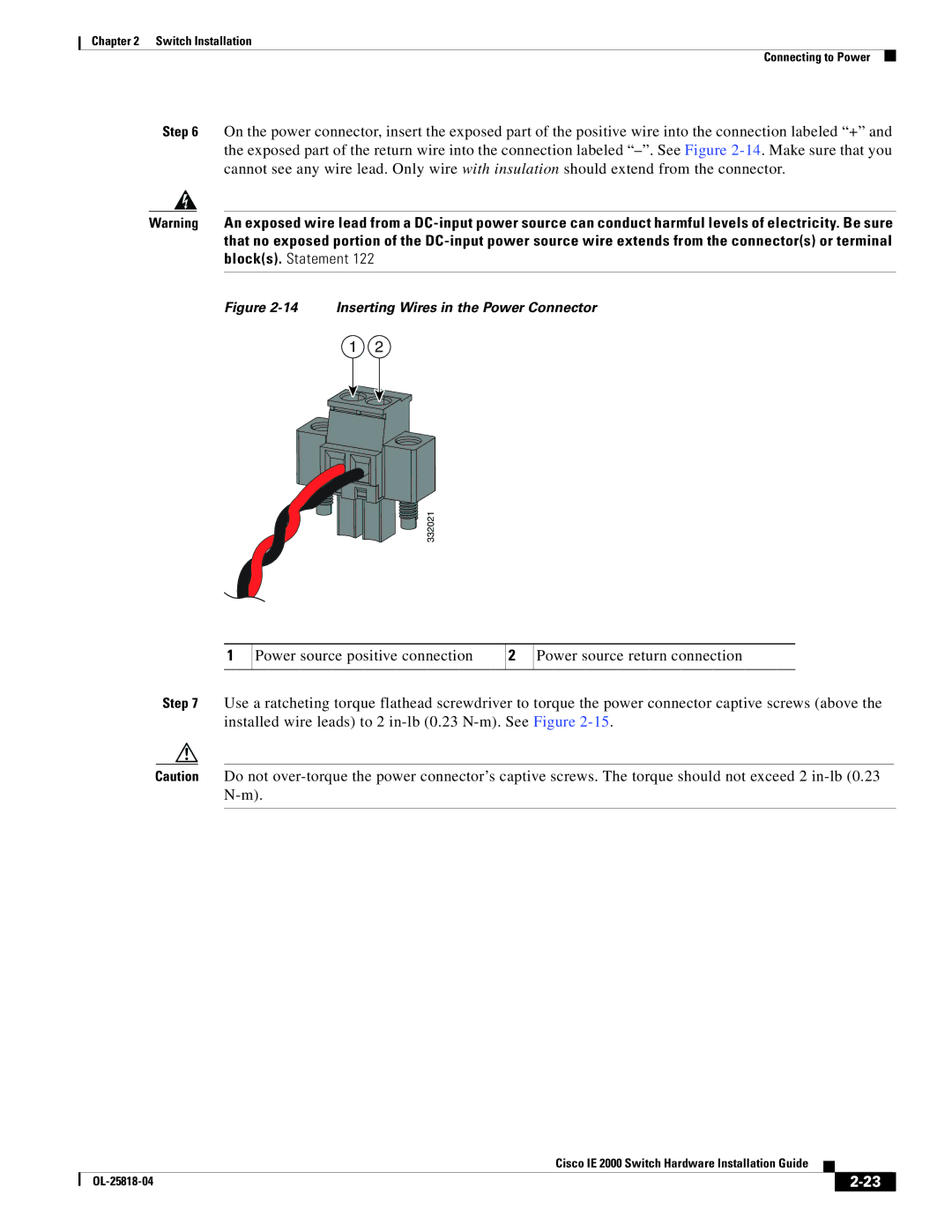
Step 6 On the power connector, insert the exposed part of the positive wire into the connection labeled “+” and the exposed part of the return wire into the connection labeled
Warning An exposed wire lead from a
Figure 2-14 Inserting Wires in the Power Connector
1 2
332021
1
Power source positive connection
2
Power source return connection
Step 7 Use a ratcheting torque flathead screwdriver to torque the power connector captive screws (above the installed wire leads) to 2
Caution Do not
|
| Cisco IE 2000 Switch Hardware Installation Guide |
|
| |
|
|
| |||
|
|
|
| ||
|
|
|
| ||