Chapter 2 Switch Installation
Connecting Destination Ports
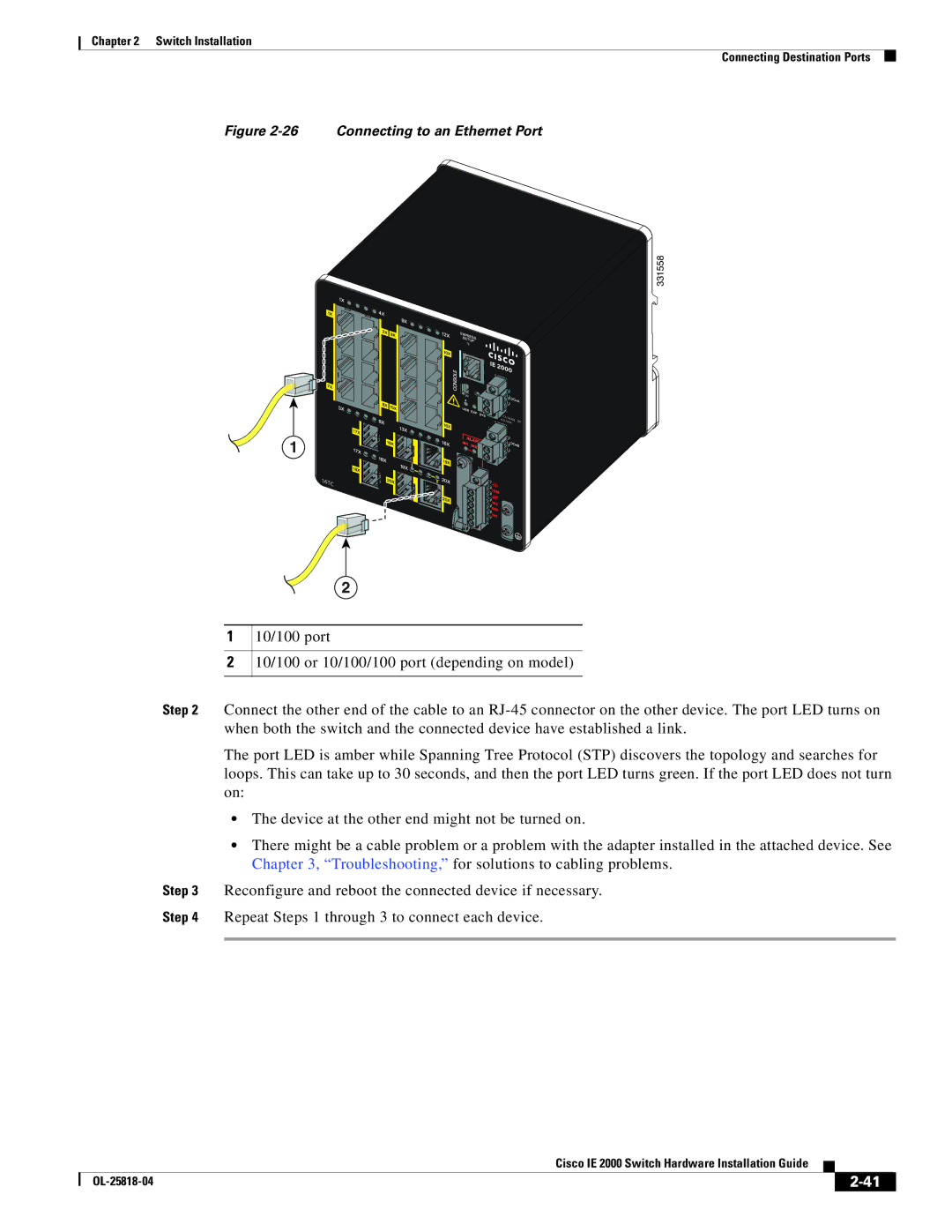
Figure 2-26 Connecting to an Ethernet Port
331558
1
16TC
2
1
2
10/100 port
10/100 or 10/100/100 port (depending on model)
Step 2 Connect the other end of the cable to an
The port LED is amber while Spanning Tree Protocol (STP) discovers the topology and searches for loops. This can take up to 30 seconds, and then the port LED turns green. If the port LED does not turn on:
•The device at the other end might not be turned on.
•There might be a cable problem or a problem with the adapter installed in the attached device. See Chapter 3, “Troubleshooting,” for solutions to cabling problems.
Step 3 Reconfigure and reboot the connected device if necessary.
Step 4 Repeat Steps 1 through 3 to connect each device.
|
| Cisco IE 2000 Switch Hardware Installation Guide |
|
| |
|
|
| |||
|
|
|
| ||
|
|
|
| ||