Installation
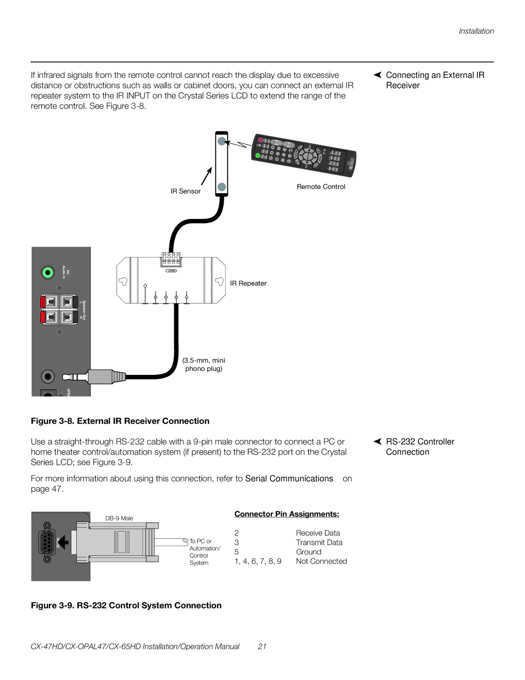
If infrared signals from the remote control cannot reach the display due to excessive | Connecting an External IR |
distance or obstructions such as walls or cabinet doors, you can connect an external IR | Receiver |
repeater system to the IR INPUT on the Crystal Series LCD to extend the range of the |
|
remote control. See Figure |
|
|
| HD | COM | 2 |
|
| M | M |
| IN | TIMER |
|
| WID |
| SWAP | 3 |
| 1 |
|
|
| 5 |
|
| T | R |
| OFF |
|
|
| |||
HDMI |
|
| 1 |
|
| 8 | 0 | S | E | U |
|
|
|
|
|
| AUDIO |
|
|
|
|
|
| C | N |
|
|
|
|
|
| 2 | |||
|
|
| COMP | 1 | 4 | 7 | 100 | F A | E | EN |
|
|
|
| SIZE |
| AUDIO |
|
|
|
|
|
| M |
|
|
|
|
|
| |||||
|
|
|
|
|
| Y |
|
|
|
|
| POSITION |
|
|
| ||
|
|
|
|
|
|
| L |
| EX |
|
| 4:3 |
|
| AUDIO | ||
|
|
|
|
|
|
|
| ISD |
|
|
|
|
|
|
|
| 1 |
|
|
|
|
|
|
|
| - |
| IT |
|
|
|
|
|
|
|
|
|
|
|
|
|
|
| VO |
|
|
| 16:9 |
| PIP |
|
| SRC |
|
|
|
|
|
|
|
|
|
|
|
|
|
|
|
|
| PIP |
IR Sensor
Remote Control
Audio | PC |
In |
|
+ | – |
Speaker Out
L R
IR
In SPDI
IR Repeater
phono plug)
Figure |
|
Use a |
|
home theater control/automation system (if present) to the | Connection |
Series LCD; see Figure |
|
For more information about using this connection, refer to Serial Communications on |
|
page 47. |
|
![]() To PC or Automation/ Control System
To PC or Automation/ Control System
Connector Pin Assignments:
2 | Receive Data |
3 | Transmit Data |
5 | Ground |
1, 4, 6, 7, 8, 9 | Not Connected |
Figure 3-9. RS-232 Control System Connection
21 |