Installation
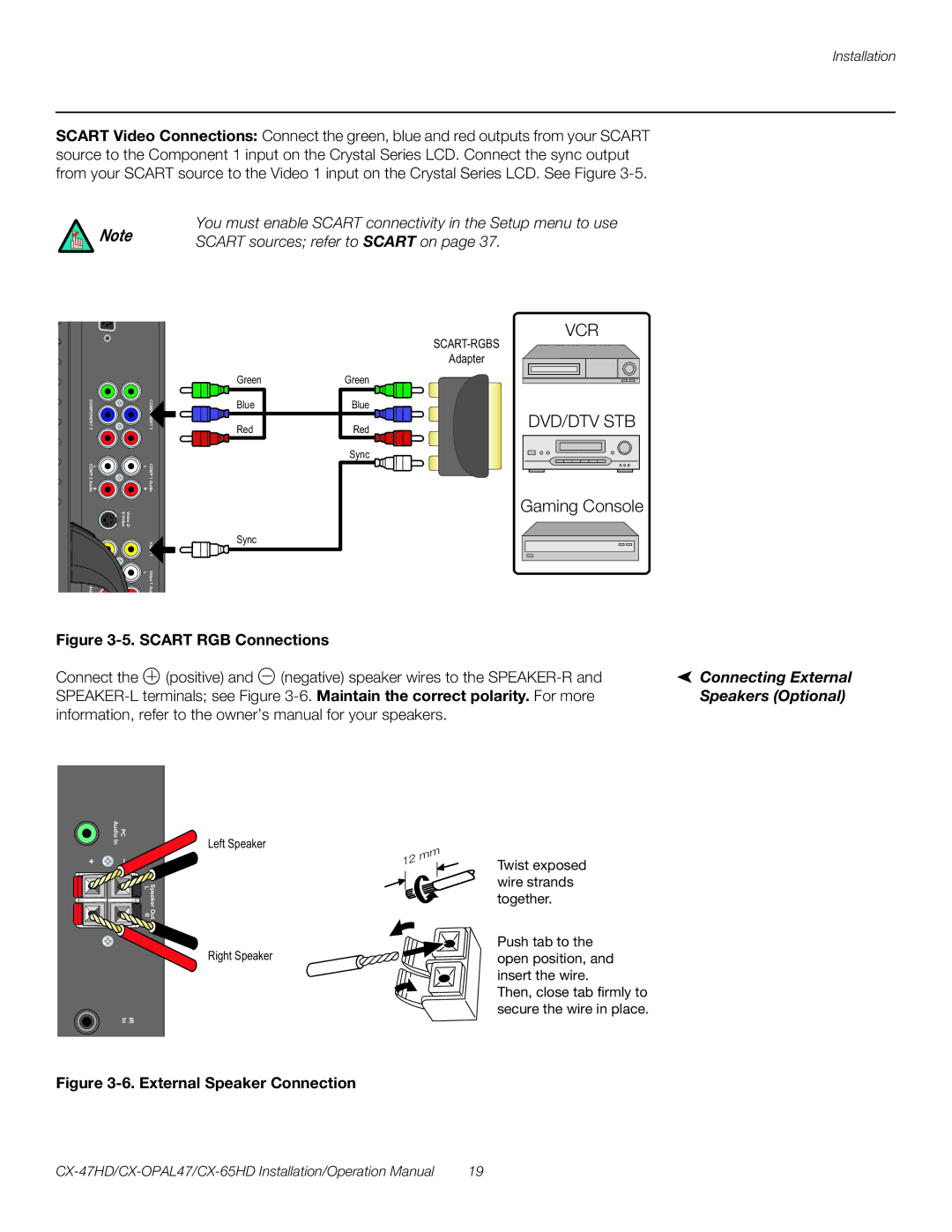
SCART Video Connections: Connect the green, blue and red outputs from your SCART source to the Component 1 input on the Crystal Series LCD. Connect the sync output from your SCART source to the Video 1 input on the Crystal Series LCD. See Figure
You must enable SCART connectivity in the Setup menu to use
Note | SCART sources; refer to SCART on page 37. |
|
VCR
Adapter
COMPONENT 2 |
| COMPONENT 1 |
L COMP | L | COMP |
R 2 Audio | R | 1 Audio |
Green
Blue
Red
Green
Blue
Red
Sync
DVD/DTV STB
Video 2/ |
| |
Video 2 |
| 1 |
L Video | L | Video |
2 Aud |
| 1 Aud |
Sync
Gaming Console
Figure |
| |||||
Connect the |
|
| (positive) and |
| (negative) speaker wires to the | Connecting External |
|
| |||||
|
|
| ||||
Speakers (Optional) | ||||||
information, refer to the owner’s manual for your speakers. |
| |||||
Audio | PC |
In |
|
+ | – |
Speaker Out
L R
IR
In
Left Speaker
Right Speaker
Twist exposed wire strands together.
Push tab to the open position, and insert the wire.
Then, close tab firmly to secure the wire in place.
Figure 3-6. External Speaker Connection
19 |
