Chapter 2 Switch Installation
Connecting to Power
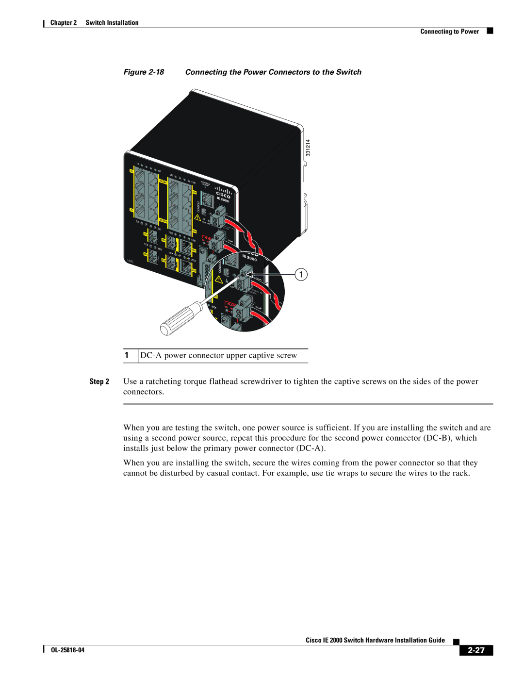
Figure 2-18 Connecting the Power Connectors to the Switch
331214
16TC
1
. |
|
| 0A |
1
Step 2 Use a ratcheting torque flathead screwdriver to tighten the captive screws on the sides of the power connectors.
When you are testing the switch, one power source is sufficient. If you are installing the switch and are using a second power source, repeat this procedure for the second power connector
When you are installing the switch, secure the wires coming from the power connector so that they cannot be disturbed by casual contact. For example, use tie wraps to secure the wires to the rack.
|
| Cisco IE 2000 Switch Hardware Installation Guide |
|
| |
|
|
| |||
|
|
|
| ||
|
|
|
| ||