Chapter 2 Switch Installation
Connecting Alarm Circuits
Wiring the External Alarms
The switch has two alarm input and one alarm output relay circuits for external alarms. The alarm input circuits are designed to sense if the alarm input is open or closed relative to the alarm input reference pin. Each alarm input can be configured as an open or closed contact. The alarm output relay circuit has a normally open and a normally closed contact.
Alarm signals are connected to the switch through the
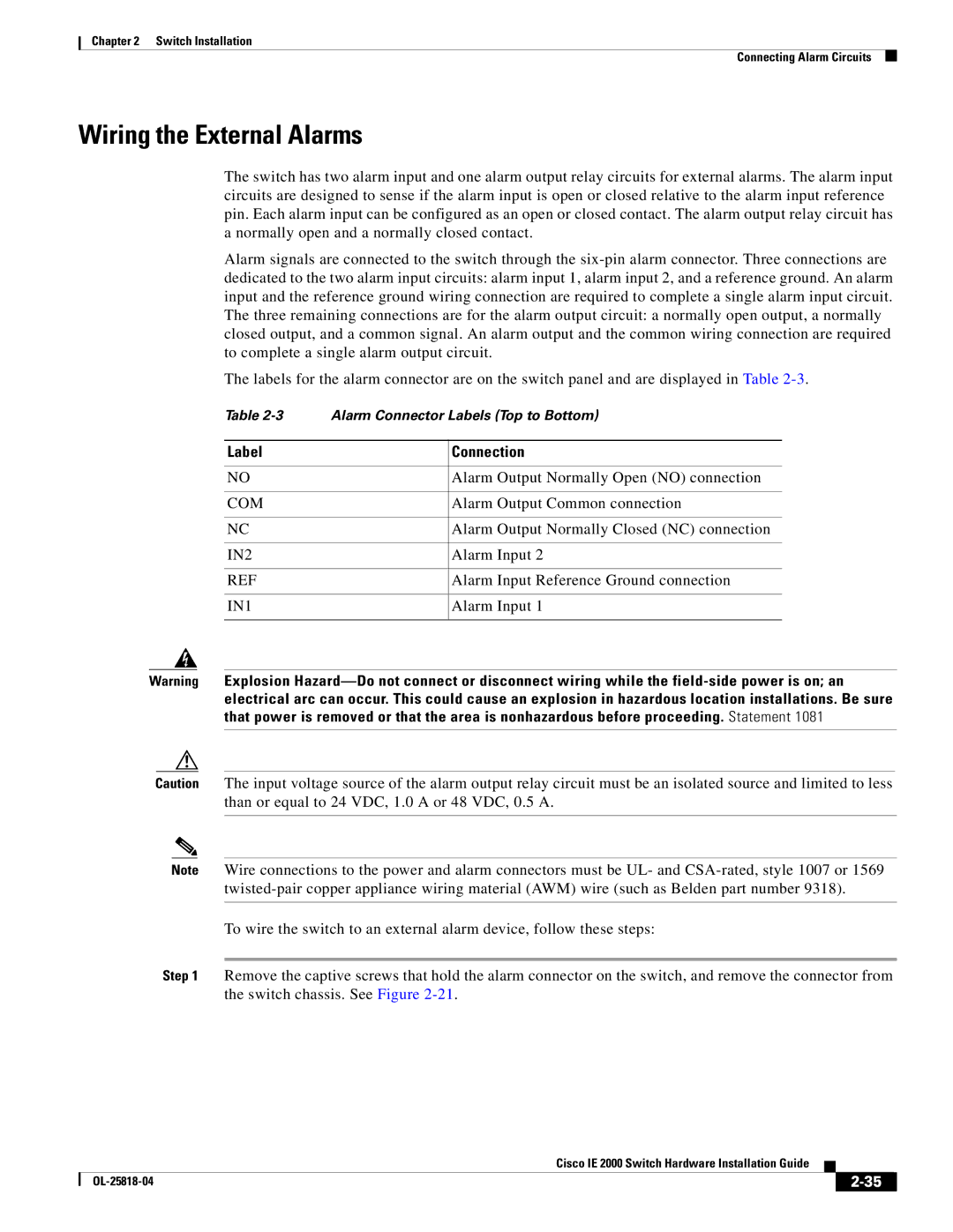
The labels for the alarm connector are on the switch panel and are displayed in Table
Table | Alarm Connector Labels (Top to Bottom) | |
|
|
|
Label |
| Connection |
|
|
|
NO |
| Alarm Output Normally Open (NO) connection |
|
|
|
COM |
| Alarm Output Common connection |
|
|
|
NC |
| Alarm Output Normally Closed (NC) connection |
|
|
|
IN2 |
| Alarm Input 2 |
|
|
|
REF |
| Alarm Input Reference Ground connection |
|
|
|
IN1 |
| Alarm Input 1 |
|
|
|
Warning Explosion
Caution The input voltage source of the alarm output relay circuit must be an isolated source and limited to less than or equal to 24 VDC, 1.0 A or 48 VDC, 0.5 A.
Note Wire connections to the power and alarm connectors must be UL- and
To wire the switch to an external alarm device, follow these steps:
Step 1 Remove the captive screws that hold the alarm connector on the switch, and remove the connector from the switch chassis. See Figure
|
| Cisco IE 2000 Switch Hardware Installation Guide |
|
| |
|
|
| |||
|
|
|
| ||
|
|
|
| ||