Chapter 1 Product Overview
Front Panel
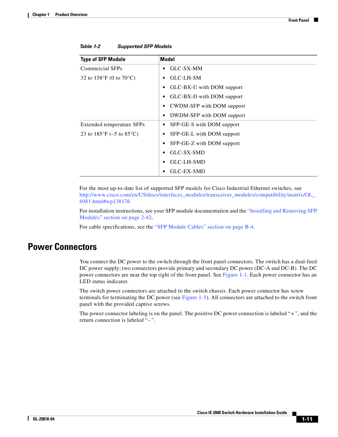
Table
Type of SFP Module | Model |
|
|
Commercial SFPs | • |
32 to 158°F (0 to 70°C) | • |
| • |
| • |
| • |
| • |
|
|
Extended temperature SFPs | • |
23 to 185°F | • |
| • |
| • |
| • |
| • |
|
|
For the most
For installation instructions, see your SFP module documentation and the “Installing and Removing SFP Modules” section on page
For cable specifications, see the “SFP Module Cables” section on page
Power Connectors
You connect the DC power to the switch through the front panel connectors. The switch has a
The switch power connectors are attached to the switch chassis. Each power connector has screw terminals for terminating the DC power (see Figure
The power connector labeling is on the panel. The positive DC power connection is labeled “+”, and the return connection is labeled
|
| Cisco IE 2000 Switch Hardware Installation Guide |
|
| |
|
|
| |||
|
|
|
| ||
|
|
|
| ||