Chapter 2 Switch Installation
Connecting Alarm Circuits
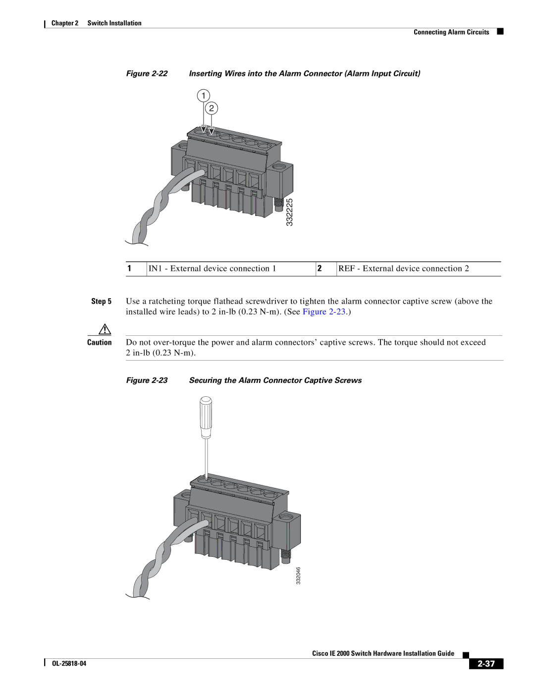
Figure 2-22 Inserting Wires into the Alarm Connector (Alarm Input Circuit)
1
2


 332225
1
IN1 - External device connection 1
2
REF - External device connection 2
Step 5 Use a ratcheting torque flathead screwdriver to tighten the alarm connector captive screw (above the installed wire leads) to 2
Caution Do not
Figure 2-23 Securing the Alarm Connector Captive Screws
332046
|
| Cisco IE 2000 Switch Hardware Installation Guide |
|
| |
|
|
| |||
|
|
|
| ||
|
|
|
| ||