Chapter 2 Switch Installation
Connecting to Power
Caution Use at least a 4 mm2 conductor to connect to the external grounding screw.
The ground lug is not supplied with the switch. You can use one of the these options:
•Single ring terminal
•Two single ring terminals
To ground the switch to earth ground by using the ground screw, follow these steps:
Step 1 Use a standard Phillips screwdriver or a ratcheting torque screwdriver with a Phillips head to remove the ground screw from the front panel of the switch. Store the ground screw for later use.
Step 2 Use the manufacturer’s guidelines to determine the wire length to be stripped.
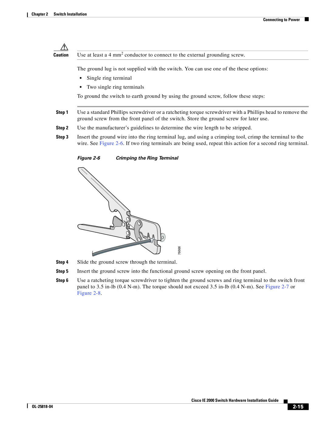
Step 3 Insert the ground wire into the ring terminal lug, and using a crimping tool, crimp the terminal to the wire. See Figure
Figure 2-6 Crimping the Ring Terminal
| 76666 |
Step 4 | Slide the ground screw through the terminal. |
Step 5 | Insert the ground screw into the functional ground screw opening on the front panel. |
Step 6 | Use a ratcheting torque screwdriver to tighten the ground screws and ring terminal to the switch front |
| panel to 3.5 |
| Figure |
|
| Cisco IE 2000 Switch Hardware Installation Guide |
|
| |
|
|
| |||
|
|
|
| ||
|
|
|
| ||