Chapter 2 Switch Installation
Connecting to Power
Table
Label | Connection |
+Positive DC power connection
– Return DC power connection
The switch panel labels can be seen in Figure
Step 3 Measure two strands of
Step 4 Using an
Figure 2-12 Stripping the Power Connection Wire
1
97489
1
0.25 in. (6.3 mm) ± 0.02 in. (0.5 mm)
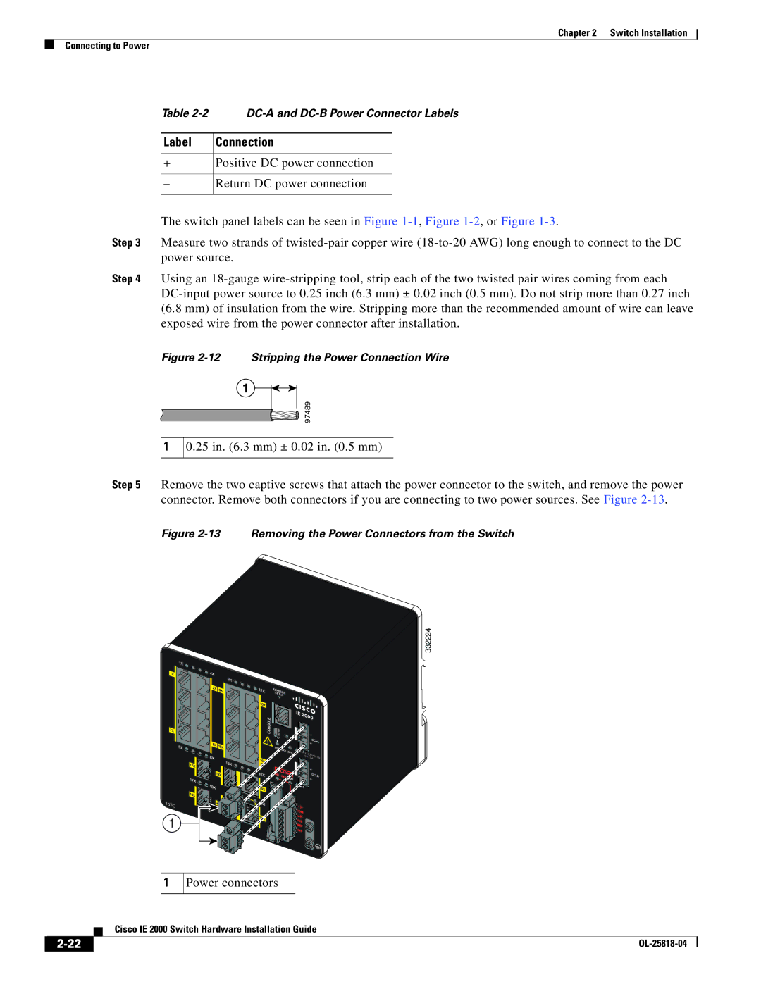
Step 5 Remove the two captive screws that attach the power connector to the switch, and remove the power connector. Remove both connectors if you are connecting to two power sources. See Figure
Figure 2-13 Removing the Power Connectors from the Switch
332224
±12/24/480.5- 3.0A
16TC
1
1
Power connectors
| Cisco IE 2000 Switch Hardware Installation Guide |