Manuals
/
Intel
/
Computer Equipment
/
Personal Computer
Intel
EMB-945T Location of Connectors and Jumpers, Locating Connectors and Jumpers Component Side
Models:
EMB-945T
1
17
59
59
Download
59 pages
43.98 Kb
14
15
16
17
18
19
20
21
Specifications
Install
Pin Signal
Password
Programming the Watchdog Timer
PnP/PCI Configurations
Entering Setup
List of Connectors
Award BIOS Setup
Setting Jumpers
Page 17
Image 17
Page 16
Page 18
Page 17
Image 17
Page 16
Page 18
Contents
Intel Core Duo/Solo Processor Up to 2.0 GHz
EMB-945T
Mini-ITX Marvell 88E8053 Ethernet
AC 97 Audio & Mini PCI
Mini-ITX
Copyright Notice
Acknowledgments
Packing List
Chapter 1 General Information
Contents
Chapter 2 Quick Installation Guide
Chapter 3 Award BIOS Setup
Appendix B Programming The Watchdog Timer
Driver Installation
Chapter
Appendix A
Chapter 1 General Information
General Information
Chapter
1.1 Introduction
Chapter 1 General Information
1.2Features
System
1.3 Specifications
Display
Page
Mini ITX
Quick Installation Guide
Chapter 2 Quick Installation Guide
2.1 Safety Precautions
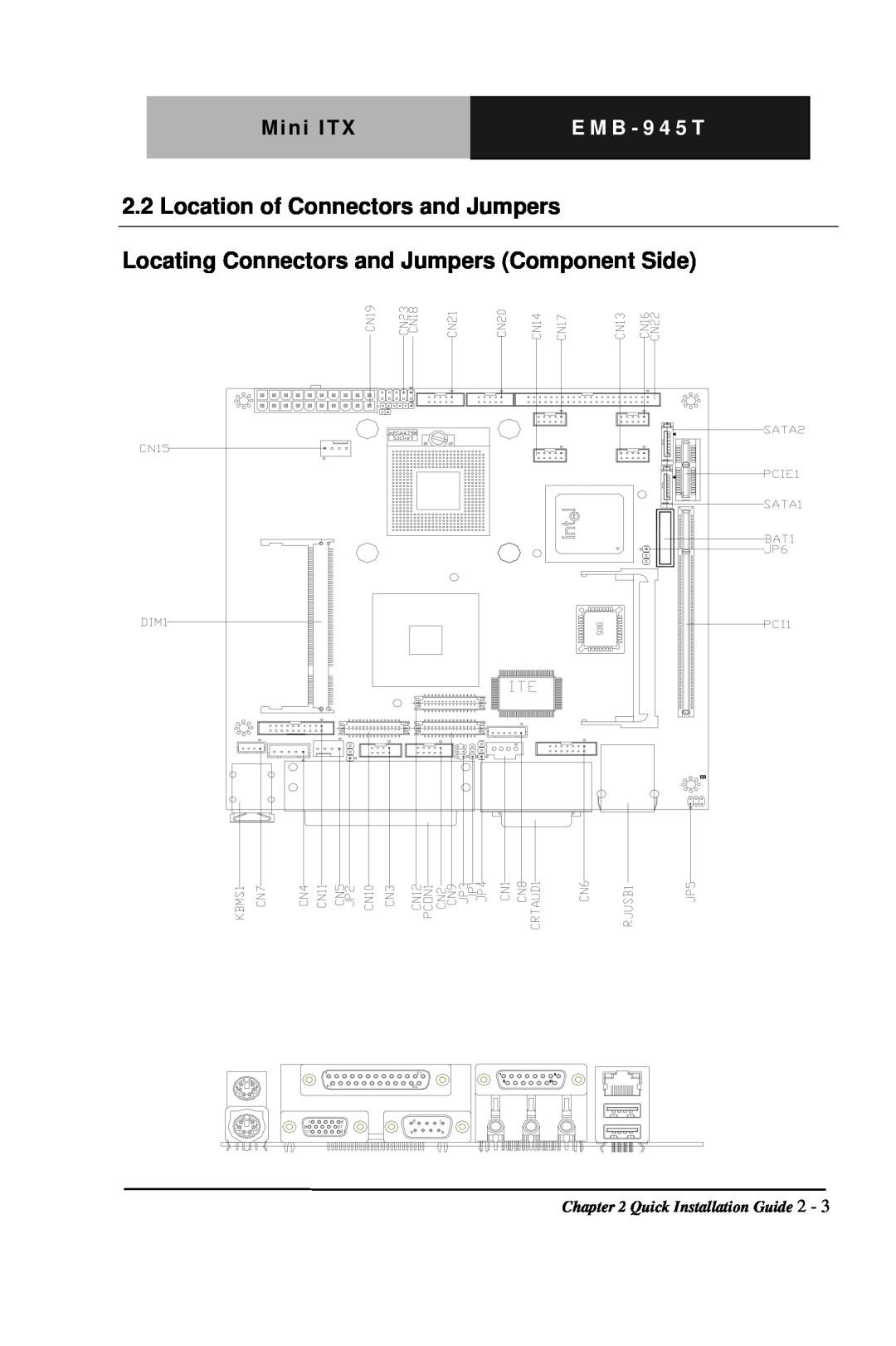
Locating Connectors and Jumpers Component Side
2.2 Location of Connectors and Jumpers
Locating Connectors and Jumpers Solder Side
2.3Mechanical Drawing Component Side
Solder Side
2.4 List of Jumpers
Jumpers
2.5 List of Connectors
Connectors
CN24
Closed
2.6 Setting Jumpers
Open
2.8 LVDS2-LCDCN10Voltage Selection JP2
2.7 LVDS1-LCDCN12Voltage Selection JP1
2.9 COM2 Ring/+5V/+12V Selection JP3
2.10 LCD INVERTER Voltage Selection JP4
2.14 Digital I/O Connector CN2
2.13 CD-INConnector CN1
2.12 Clear CMOS JP6
Function
2.16 Internal Keyboard Connector CN4
2.15 TV Out Connector CN3
8 in
8 out
2.18 Audio 5.1 Channel / SPDIF Connector CN6
2.17 Fan2 Connector CN5
2.19 Internal Mouse Connector CN7
2.20 LCD Inverter Connector CN8
2.21 PCI Express Slot For AAEON CN9
2.23 DVI Connector CN11
2.22 LVDS2-LCDConnector CN10
2.24 LVDS1-LCDConnector CN12
2.26 COM3 RS-232Serial Port Connector CN14
2.25 COM6 RS-232Serial Port Connector CN13
2.27 Fan1 ConnectorCN15
Pin Signal
2.30 IrDA Connector CN18
2.28 COM5 RS-232Serial Port Connector CN16
2.29 COM4 RS-232Serial Port Connector CN17
2.32 USB Connector CN20
2.31 ATX Power Connector CN19
2.33 USB ConnectorCN21
Mini ITXE M B - 9 4 5 T
2.34 EIDE Connector CN22
2.36 COM2 RS-232Serial Port Connector
2.35 Front Panel Connector CN23
Chapter 3 Award BIOS Setup
Award BIOS Setup
3.1System Test and Initialization
System configuration verification
Standard CMOS Features
Entering Setup
Advanced BIOS Features
3.2Award BIOS Setup
Power Management Setup
Advanced Chipset Features
PnP/PCI Configurations
Load Fail-SafeDefaults
Exit Without Saving
Set Supervisor/User Password
Save and Exit Setup
Chapter 4 Driver Installation
Driver Installation
Follow the sequence below to install the drivers
SetupYukonWin.exe
4.1 Installation
Step 4 - Install Realtek AC97 codec Driver
Appendix A I/O Information A-1
I/O Information
Appendix
Appendix A I/O Information A-2
A.1 I/O Address Map
Appendix A I/O Information A-3
A.2 Memory Address Map A.3 IRQ Mapping Chart
Appendix A I/O Information A-4
A.4 DMA Channel Assignments
Appendix B Programming the Watchdog Time B-1
Programming the Watchdog Timer
Appendix B Programming the Watchdog Time B-2
Configuring Sequence Description
B.1 Programming
2 Modify the Data of the Registers
1 Enter the MB PnP Mode
3 Exit the MB PnP Mode
Appendix B Programming the Watchdog Timer B-3
Appendix B Programming the Watchdog Time B-4
WatchDog Timer Configuration Registers
Configure Control Index=02h
Appendix B Programming the Watchdog Timer B-5
B.2 IT8712 Watchdog Timer Initial Program
game port enable mov cl, call Set Logic Device
CALL Read Configuration Data CMP AL,87h
RET Exit Configuration Mode ENDP
CALL Read Configuration Data CMP AL,12h
Read Configuration Data PROC NEAR
MOV DX,WORD PTR CS Cfg Port+06h IN AL,DX RET
push ax push cx xchg al,cl mov cl,07h
END Main
call Superio Set Reg pop cx pop ax ret
Set Logic Device endp
Top
Page
Image
Contents