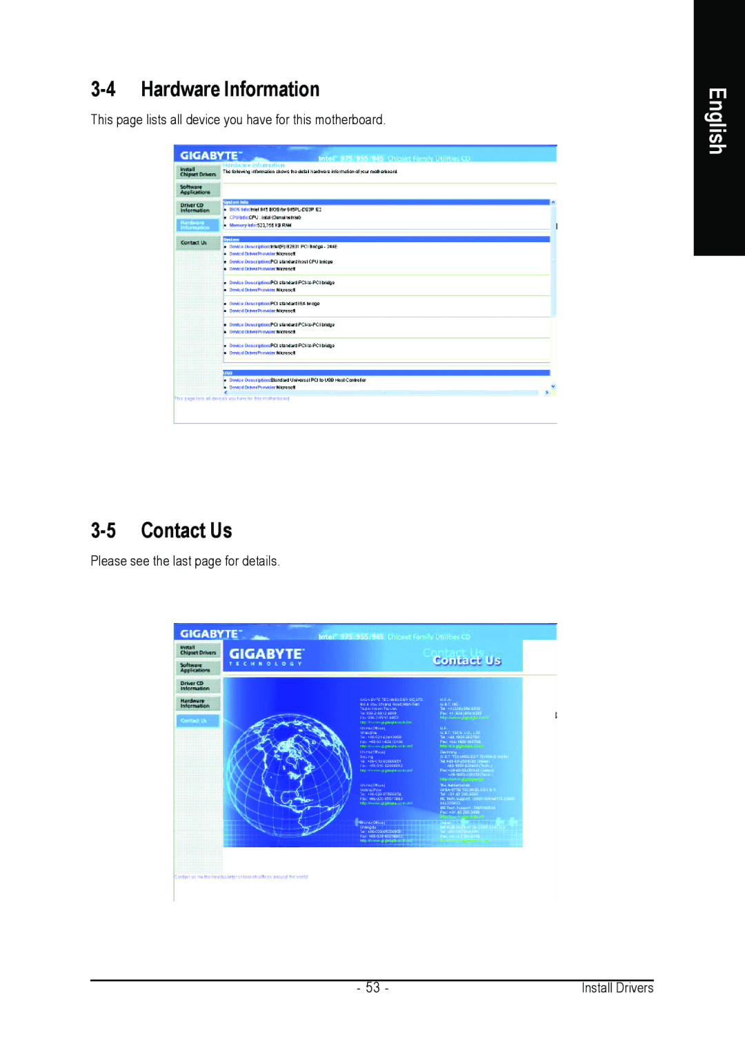
3-4 Hardware Information
This page lists all device you have for this motherboard.
3-5 Contact Us
Please see the last page for details.
English
- 53 - | Install Drivers |
This page lists all device you have for this motherboard.
Please see the last page for details.
- 53 - | Install Drivers |