INSTALLATIONS
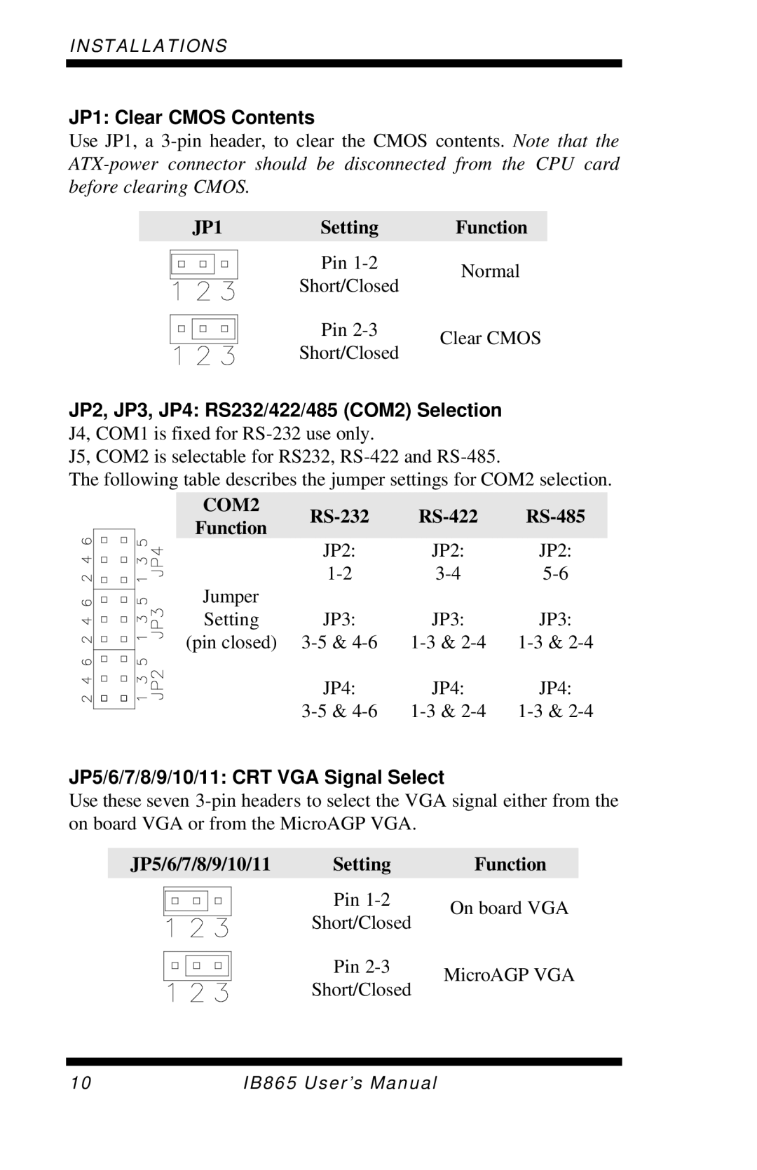
JP1: Clear CMOS Contents
Use JP1, a
JP1 | Setting | Function |
| Pin | Normal |
| Short/Closed | |
|
| |
| Pin | Clear CMOS |
| Short/Closed | |
|
|
JP2, JP3, JP4: RS232/422/485 (COM2) Selection J4, COM1 is fixed for
J5, COM2 is selectable for RS232,
The following table describes the jumper settings for COM2 selection.
| COM2 |
|
|
| |||
| Function |
|
|
| |||
|
|
|
|
|
|
| |
|
|
| JP2: |
| JP2: |
| JP2: |
| Jumper | ||||||
|
|
|
|
|
|
| |
| Setting |
| JP3: |
| JP3: |
| JP3: |
| (pin closed) | ||||||
|
|
| JP4: |
| JP4: |
| JP4: |
|
| ||||||
JP5/6/7/8/9/10/11: CRT VGA Signal Select
Use these seven
JP5/6/7/8/9/10/11 | Setting | Function |
| Pin | On board VGA |
| Short/Closed | |
|
| |
| Pin | MicroAGP VGA |
| Short/Closed | |
|
|
10 | IB865 User’s Manual |