Version
USER’S Manual
Acknowledgments
Table of Contents
IB865 User’s Manual
Introduction
Checklist
Product Description
CPU
Specifications
Board Dimensions
Installations
Installing the CPU
Installing the Memory
ATX Power Installation
Setting the Jumpers
Jumper Locations on IB865
JP5/6/7/8/9/10/11 CRT VGA Signal Select
JP1 Clear Cmos Contents
JP14 DiskOnChip Address Select
JP13 Primary LAN Enable/Disable
J4 TV out Connector
JP2 Panel Voltage Setting
J2, J3 Lvds Connectors 2nd channel, 1st channel
JP2 Lvds Panel Power Select
JP1 TV Type Select
J2 CRT2 / TV-Out Connector
Jumper and Connectors on IBA110 J1 Tmds Panel Connector
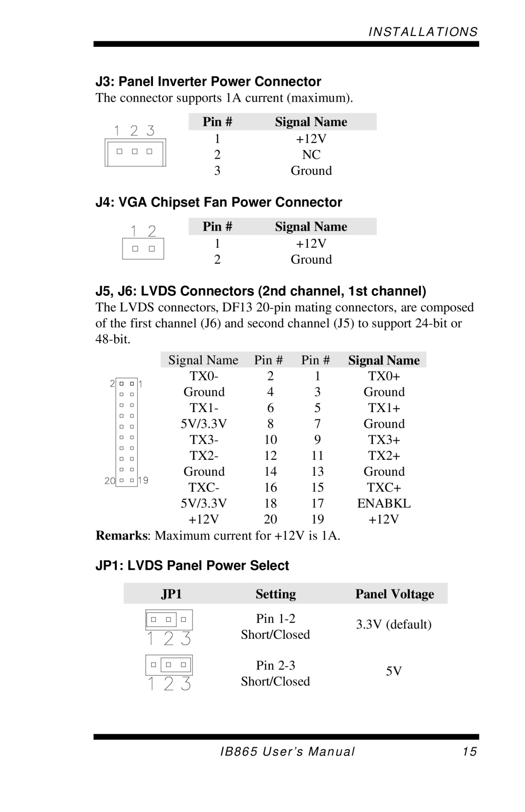
JP1 Lvds Panel Power Select
J3 Panel Inverter Power Connector
J4 VGA Chipset Fan Power Connector
J5, J6 Lvds Connectors 2nd channel, 1st channel
SW1 Lvds Resolution Select
Connectors on IB865
Connector Locations on IB865
IRQ15
IDE1, IDE2 Eide Connectors
CN1 ATX 12V/+12V Power Connector
FDD1 Floppy Drive Connector
J8, J9 System Fan Power Connector
CN2, CN3 USB Connectors
J3 CPU Fan Power Connector
J7 External ATX Power Connector
Speaker Pins 1
J1 System Function Connector
SMI/Hardware Switch Pins 6
J4, J5 COM1 and COM2 Serial Ports Connector
J2 Parallel Port Connector
J13, J14 Serial ATA Sata Connectors
J10 Wake On LAN Connector
J11 External Audio Connector
J12 CD-In Audio Connector
J16, J18 External PS/2 Keyboard and Mouse Connector
J15 VGA CRT Connector
J17 IrDA Connector
AGP1 MicroAGP Connector for IBA110 / IBA120
J19 PS/2 Keyboard and Mouse Connector
J20 Primary RJ45 Connector
J21 Gigabit LAN RJ45 Connector
Sample Code
Watchdog Timer Configuration
Name DisableWatchdog None
Name LockChip None
Bios Setup
Bios Setup
Bios Introduction
Phoenix AwardBIOS Cmos Setup Utility
Date
Standard Cmos Setup
IDE Primary HDDs / IDE Secondary HDDs
Time
Drive a / Drive B
Halt On
Video
Virus Warning
Advanced Bios Features
CPU Feature
Hard Disk / CD-ROM Boot Priority
Boot Up Floppy Seek
Quick Power On Self Test
First/Second/Third Boot Device
Boot Other Device
Security Option
Typematic Delay Msec
Apic Mode
Typematic Rate Chars/Sec
Dram Timing Selectable
Advanced Chipset Features
Active to Precharge Delay
Dram RAS# to CAS# Delay
AGP Aperture Size
On-Chip Frame Buffer Size
Boot Display
Video Connector
On-Chip VGA
Integrated Peripherals
IDE Primary/Secondary Master/Slave Udma
IDE HDD Block Mode
OnChip Primary/Secondary PCI IDE
IDE Primary/Secondary Master/Slave PIO
Onboard Lan Boot ROM
Uart Mode Select
Parallel Port Mode
Power After PWR-Fail
Power Supply Type
Power Management Setup
Acpi Function
Video Off Method
Power Management
Suspend Mode
HDD Power Down
CPU THRM-Throttling
Power On by Ring
Resume by Alarm
Reload Global Timer Events
Resources Controlled by
PNP/PCI Configurations
PNP OS Install
Reset Configuration Data
Temperature/CPU/Chassis Fan Failure Warning
CPU Warning Temperature
Temperatures/Fan Speeds/Voltages
Shutdown Temperature
Auto Detect PCI Clk
Frequency/Voltage Control
Spread Spectrum
Save & Exit Setup
Load Fail-Safe Defaults
Load Setup Defaults
Set Supervisor/User Password
Drivers Installation
Intel 865G Chipset Software Intallation Utility
Drivers Installation
Drivers Installation
Intel 865G Chipset Graphics Driver
Drivers Installation
Realtek AC97 Codec Audio Driver Installation
Intel PRO LAN Drivers Installation