Manuals
/
Intel
/
Computer Equipment
/
Computer Hardware
Intel
IMB200VGE
user manual
Installation
Models:
IMB200VG
IMB200VGE
IMB200
1
20
77
77
Download
77 pages
51.38 Kb
17
18
19
20
21
22
23
24
Specifications
Install
Password
Load Fail-Safe Default
Delay prior to Thermal
Dimension
PNP/PCI Configuration
Bios Setup
Jumpers and Connectors
Chapter Award Bios Utility
Page 20
Image 20
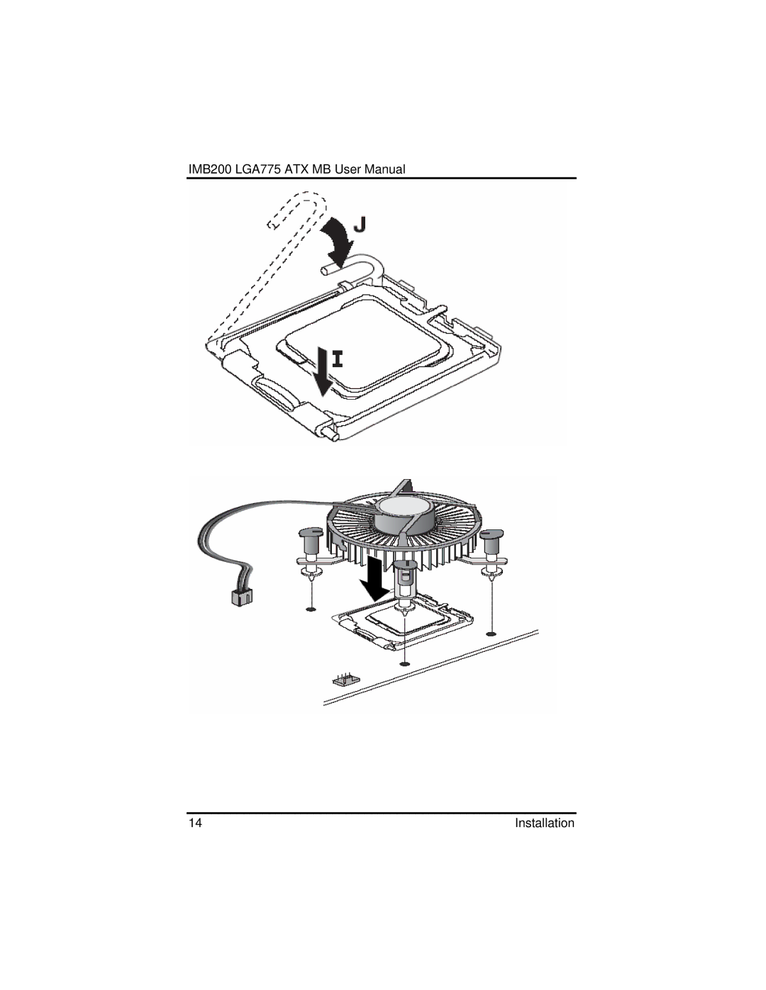
IMB200 LGA775 ATX MB User Manual
14
Installation
Page 19
Page 21
Page 20
Image 20
Page 19
Page 21
Contents
IMB200
Disclaimers
ESD Precautions
Jumpers and Connectors
Installation
Chapter Introduction
Hardware Description
Installing VGA driver
Chapter Installing LAN Driver
Chapter Award Bios Utility
P e n d i x a Watchdog Timer P e n d i x B PCI IRQ Routing
Page
Introduction
General Description
Specifications
¾ CPU Socket LGA775
Utilities Supported
Ordering information
Board Dimensions
Jumpers and Connectors
Board Layout
Jumper Settings
Jumper Default Setting Jumper Setting
Clear Cmos Setting JP7
CF Power Setting JP9
Connectors
CN7
PCI1~
Installation
CPU Installation
Installation
Installation
Installation
Installation
Installation
Installation
Installing ATX Power Supply
Installing the Memory
Installation
General Output Connector CN37
Hardware Description
Enhance IDE1/IDE2 connecotor-IDE1 and IDE2
Floppy Disk Connector-FDD
Display interface-CN1
Parallel Port Connector
COM1 Port Connector-CN2
Hardware Description
Hardware Description
USB USB USB USB
Serial ATA Connectors-CN28/CN29
Hardware Description
16 CD/In Connector-CN9
17 CPU/System FAN Connector- CN23/CN24
Installing VGA driver
Driver Disks’ Contents
Windows 2000 VGA Driver Installation
Introduction
Page
Windows XP VGA Driver Installation
Drivers Supported
Installing LAN Driver
Features
Bios Setup
Award Bios Utility
Bios Introduction
Page
Standard Cmos Setup
Date
Time
Drive a type/Drive B type
Halt On
Advanced Bios Features
CPU Feature
Delay prior to Thermal
Execute Disable Bit
Thermal Management
Limited Cupid MaxVal
Quick Power On Self Test
Virus Warning
First/Second/Third Boot Device
Boot Other Device
Boot Up Floppy Seek
Swap Floppy Drive
Boot Up NumLock Status
Apic Mode
Advanced Chipset Features
Darm Timing Selectable
Active Precharge Delay
Dram RAS# to CAS# Delay
System Bios Cacheable
Video Bios Cacheable
Init Display First
Memory Hole At 15M-16M
AGP Aperture Size MB
On-Chip VGA
On-Board Frame Buffer Size
Integrated Peripherals
On-Chip IDE Device
On-Chip Primary PCI IDE
IDE Primary Master PIO
IDE Primary Slave PIO
IDE Primary Master Udma
Onboard Device
On-Chip Serial ATA
USB Controller
USB 2.0 Controller
USB Keyboard Support
AC97 Audio
Uart Mode Select
UR2 Duplex Mode
Super IO Device
Onboard FDC Controller
Parallel Port Mode
ECP mode Use DMA
Onboard Uart 3/4
Onboard Parallel Port
Onboard Uart 3/4 IRQ
Spread Spectrum
Power Management Setup
Power Management
Acpi Function
Acpi Suspend Type
Suspend Mode
HDD Power Down
Video Off Method
Video Off In Suspend
„ PWN After PWR-Fail
Power On function
Wake-Up By PCI card
Reset Configuration Data
PNP/PCI Configuration
PNP OS Installed
„ Resource controlled by
„ PCI /VGA Palette Snoop
PC Health Status
Frequency/Voltage Control
System FAN2 Speed
+3.3V/+5V/+12V/-12V/-5V/VBATV/5VSB
CPU Clock Ratio
Supervisor/User Password Setting
Load Fail-Safe Default
Load Optimized Default
Enter Password
Exit Setting
Save to Cmos and Exit Y/N? Y
Quit without saving Y/N? Y
P e n d i x a Watchdog Timer
P e n d i x B PCI IRQ Routing
AppendixC Detailed memory Addess Mapping
AppendixD I/O Shield
Top
Page
Image
Contents