Intel® LXD972M Transceiver Demo Board (Board Rev A1)
2.3Quick-Start Checklists
Use the
The following
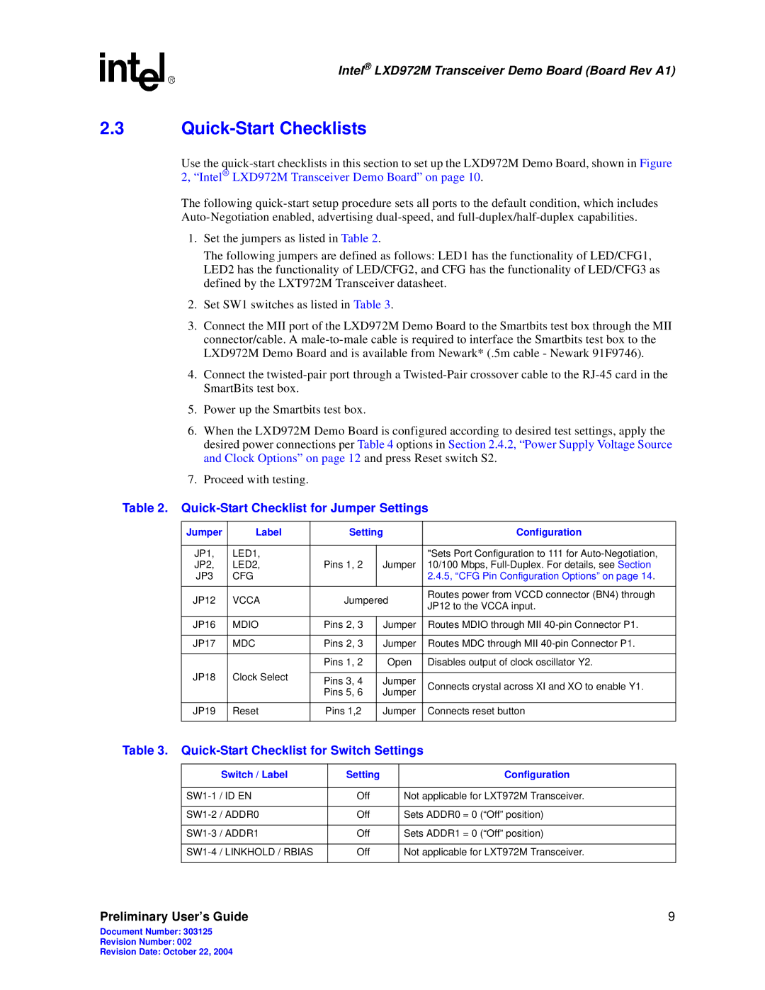
1.Set the jumpers as listed in Table 2.
The following jumpers are defined as follows: LED1 has the functionality of LED/CFG1, LED2 has the functionality of LED/CFG2, and CFG has the functionality of LED/CFG3 as defined by the LXT972M Transceiver datasheet.
2.Set SW1 switches as listed in Table 3.
3.Connect the MII port of the LXD972M Demo Board to the Smartbits test box through the MII connector/cable. A
4.Connect the
5.Power up the Smartbits test box.
6.When the LXD972M Demo Board is configured according to desired test settings, apply the desired power connections per Table 4 options in Section 2.4.2, “Power Supply Voltage Source and Clock Options” on page 12 and press Reset switch S2.
7.Proceed with testing.
Table 2. Quick-Start Checklist for Jumper Settings
Jumper | Label | Setting | Configuration | ||
|
|
|
|
| |
JP1, | LED1, |
|
| "Sets Port Configuration to 111 for | |
JP2, | LED2, | Pins 1, 2 | Jumper | 10/100 Mbps, | |
JP3 | CFG |
|
| 2.4.5, “CFG Pin Configuration Options” on page 14. | |
|
|
|
|
| |
JP12 | VCCA | Jumpered | Routes power from VCCD connector (BN4) through | ||
JP12 to the VCCA input. | |||||
|
|
|
| ||
|
|
|
|
| |
JP16 | MDIO | Pins 2, 3 | Jumper | Routes MDIO through MII | |
|
|
|
|
| |
JP17 | MDC | Pins 2, 3 | Jumper | Routes MDC through MII | |
|
|
|
|
| |
|
| Pins 1, 2 | Open | Disables output of clock oscillator Y2. | |
JP18 | Clock Select |
|
|
| |
Pins 3, 4 | Jumper | Connects crystal across XI and XO to enable Y1. | |||
|
| ||||
|
| Pins 5, 6 | Jumper | ||
|
|
| |||
|
|
|
|
| |
JP19 | Reset | Pins 1,2 | Jumper | Connects reset button | |
|
|
|
|
| |
Table 3. Quick-Start Checklist for Switch Settings
| Switch / Label | Setting | Configuration |
|
|
|
|
/ ID EN | Off | Not applicable for LXT972M Transceiver. | |
|
|
|
|
/ ADDR0 | Off | Sets ADDR0 = 0 (“Off” position) | |
|
|
|
|
/ ADDR1 | Off | Sets ADDR1 = 0 (“Off” position) | |
|
|
|
|
/ LINKHOLD / RBIAS | Off | Not applicable for LXT972M Transceiver. | |
|
|
|
|
Preliminary User’s Guide | 9 |
Document Number: 303125
Revision Number: 002
Revision Date: October 22, 2004