INSTALLATIONS
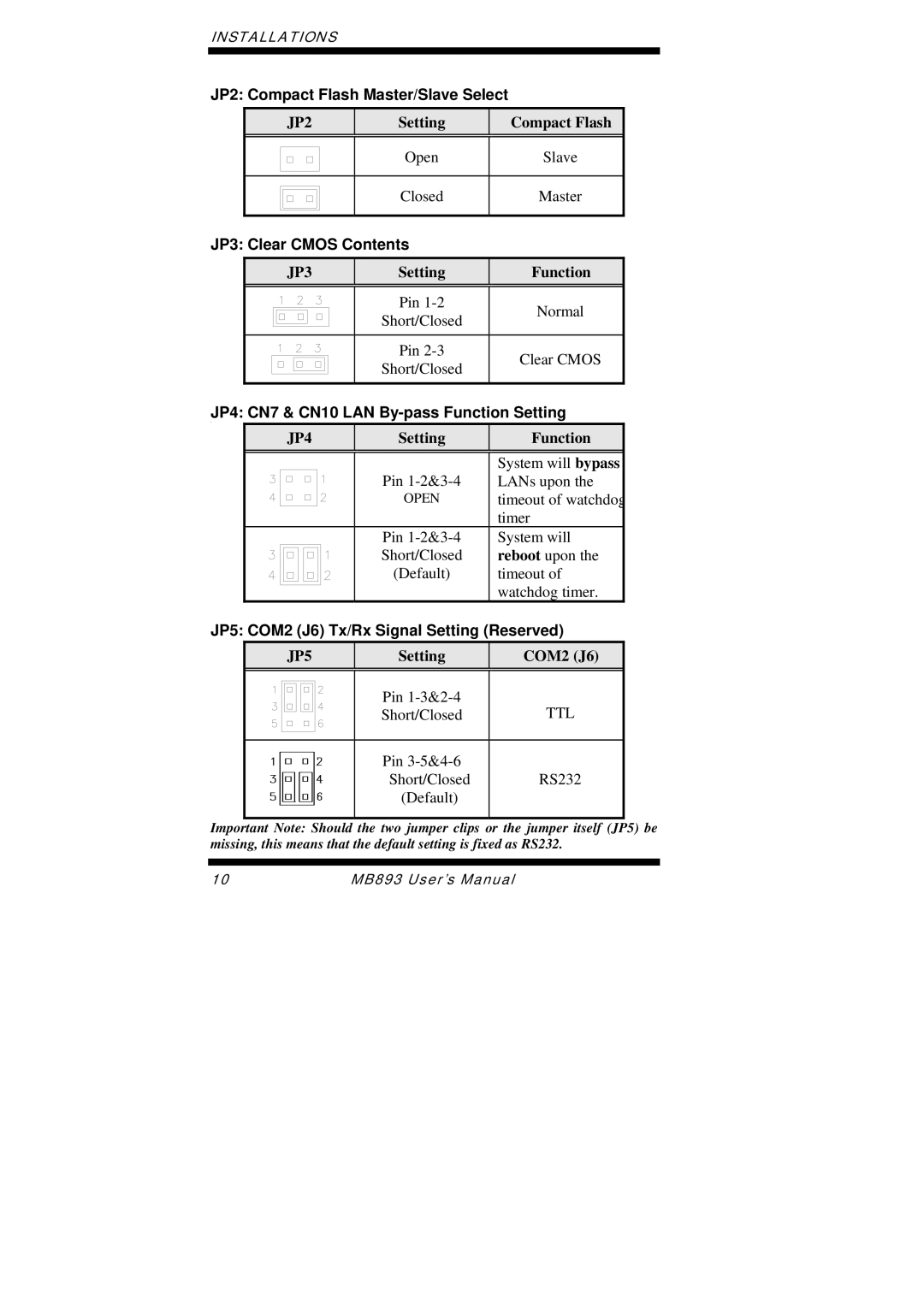
JP2: Compact Flash Master/Slave Select
JP2
Setting
Compact Flash
|
|
| Open | Slave |
|
|
| ||
|
|
|
|
|
|
|
|
|
|
|
|
| Closed | Master |
|
|
| ||
|
|
|
|
|
|
|
|
|
|
|
|
|
|
|
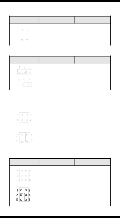
JP3: Clear CMOS Contents
JP3
Setting
Function
| Pin | Normal |
| Short/Closed | |
|
| |
|
|
|
| Pin | Clear CMOS |
| Short/Closed | |
|
| |
|
|
|
JP4: CN7 & CN10 LAN By-pass Function Setting
[
JP4 |
| Setting | Function |
|
|
|
|
|
| Pin | System will bypass |
|
| LANs upon the | |
|
| OPEN | timeout of watchdog |
|
|
| timer |
|
| Pin | System will |
|
| Short/Closed | reboot upon the |
|
| (Default) | timeout of |
|
|
| watchdog timer. |
JP5: COM2 (J6) Tx/Rx Signal Setting (Reserved)
JP5
Setting
COM2 (J6)
|
|
|
|
| Pin | TTL |
|
|
|
|
| ||
|
|
|
|
| Short/Closed | |
|
|
|
|
| ||
|
|
|
|
|
|
|
|
|
|
|
| Pin | RS232 |
|
|
|
|
| Short/Closed | |
|
|
|
|
| (Default) |
|
|
|
|
|
|
| |
|
|
|
|
|
|
|
Important Note: Should the two jumper clips or the jumper itself (JP5) be missing, this means that the default setting is fixed as RS232.
10 | MB893 User’s Manual |