INSTALLATIONS
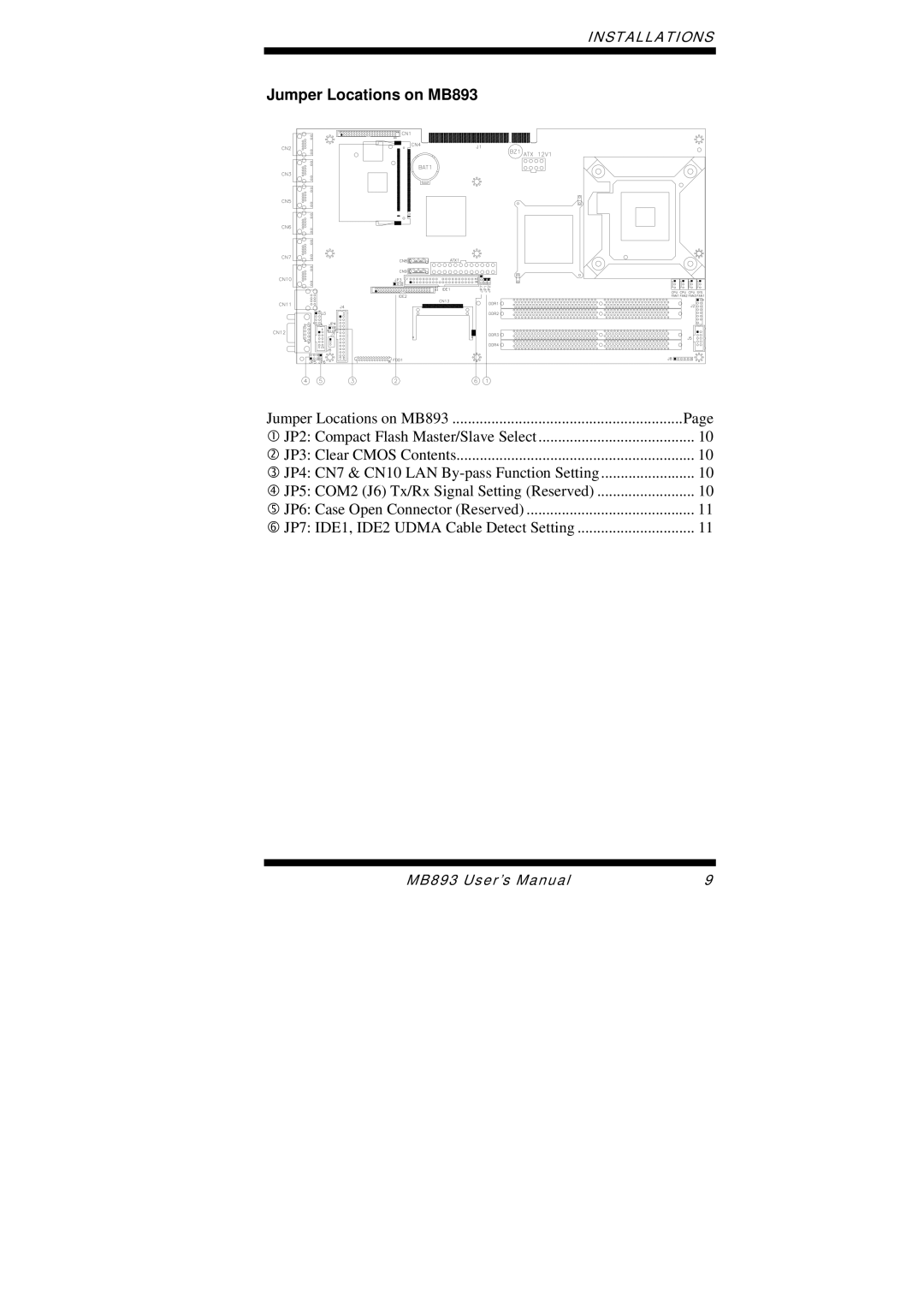
Jumper Locations on MB893
Jumper Locations on MB893 | Page |
c JP2: Compact Flash Master/Slave Select | 10 |
d JP3: Clear CMOS Contents | 10 |
e JP4: CN7 & CN10 LAN | 10 |
f JP5: COM2 (J6) Tx/Rx Signal Setting (Reserved) | 10 |
g JP6: Case Open Connector (Reserved) | 11 |
h JP7: IDE1, IDE2 UDMA Cable Detect Setting | 11 |
MB893 User’s Manual | 9 |
