INSTALLATIONS
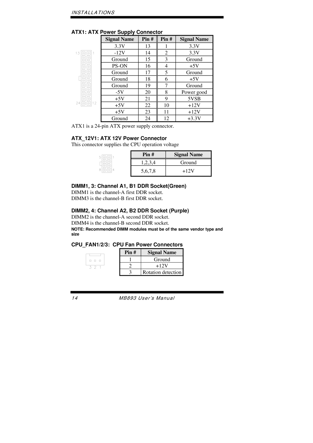
ATX1: ATX Power Supply Connector
Signal Name | Pin # | Pin # | Signal Name |
3.3V | 13 | 1 | 3.3V |
14 | 2 | 3.3V | |
Ground | 15 | 3 | Ground |
16 | 4 | +5V | |
Ground | 17 | 5 | Ground |
Ground | 18 | 6 | +5V |
Ground | 19 | 7 | Ground |
20 | 8 | Power good | |
+5V | 21 | 9 | 5VSB |
+5V | 22 | 10 | +12V |
+5V | 23 | 11 | +12V |
Ground | 24 | 12 | +3.3V |
ATX1 is a
ATX_12V1: ATX 12V Power Connector
This connector supplies the CPU operation voltage
Pin #
Signal Name
1,2,3,4 | Ground |
5,6,7,8 | +12V |
|
|
DIMM1, 3: Channel A1, B1 DDR Socket(Green) DIMM1 is the
DIMM3 is the
DIMM2, 4: Channel A2, B2 DDR Socket (Purple) DIMM2 is the
[
NOTE: Recommended DIMM modules must be of the same vendor type and size
CPU_FAN1/2/3: CPU Fan Power Connectors
| Pin # | Signal Name |
|
1Ground
2+12V
3Rotation detection
14 | MB893 User’s Manual |