PCM-9387
User’s Manual
Copyright
Model No. List Description
Packing List
Additional Information and Assistance
Page
PCM-9387 User’s Manual
Contents
Chapter Chipset Software Installation Utility
Integrated Peripherals
Chapter Audio Setup
Appendix D AT/ATX Power setting
PCM-9387 User’s Manual Xii
General Information
Introduction
Features
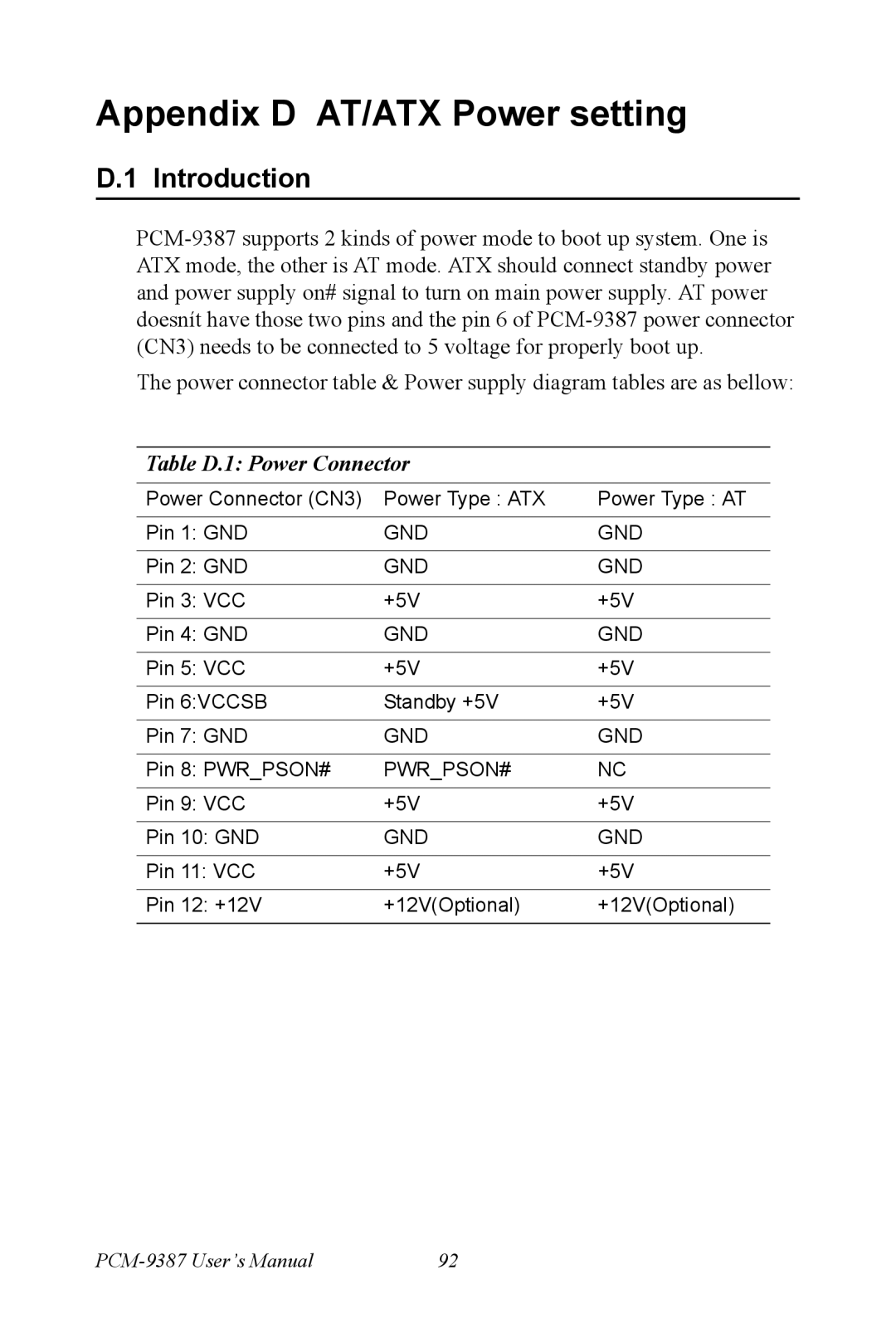
Introduction
2 VGA/LVDS Interface
Specifications
Standard 3.5 Biscuit SBC Functions
Mechanical and Environmental
Ethernet Interface
Audio Function
Board layout dimensions
Board layout DimensionsComponent Side
Board layout DimensionsSolder Side
Installation
Jumpers
Jumpers
Jumper Location
Jumper Settings
Audio Power SelectorJ1
COM2 Setting
LCD Power Setting J6
PCI VIO JP1
Cmos clear
Connectors
Connectors
Locating Connectors
Jumpers and Connectors Drawing component side
Connectors solder side
Setting Jumpers
Installing SO-DIMM
IDE, Cdrom hard drive connector CN6
Parallel port connector CN13
Connecting the hard drive
Solid State Disk
CompactFlash CN21
Power connectors CN3
Keyboard and PS/2 mouse connector CN14
Power & HDD LED Connector CN10
14 VGA/LCD/LVDS interface connections
COM port connector CN8,CN19
Audio interfaces CN2
Ethernet configuration
Watchdog timer configuration
USB connectors CN5,CN9
15.1 100Base-T/1000Base-T connector CN12
Gpio General Purpose Input Output CN7
Chipset Software Installation Utility
Before you begin
Ers
Installing the CSI Utility
PCM-9387 User’s Manual
Page
PCM-9387 User’s Manual
Award Bios Setup
Cmos RAM Auto-backup and Restore
Entering Setup
Award Bios Setup initial screen
Standard Cmos Setup
Advanced Bios Features
Quick Power On Self Test
First/Second/Third/Other Boot Device
Virus Warning
2 L1 & L2 Cache
Boot UP Floppy Seek
Boot Up NumLock Status
Typematic Rate Setting
Typematic Delay msec
IDE Master/Slave PIO/UDMA Mode
Integrated Peripherals
MPS Version Control For OS
On-Chip Secondary PCI IDE
IDE HDD Block Mode
Uart Mode Select
IR Transmission Delay
USB Controller
14 UR2 Duplex Mode
Parallel Port Mode
EPP Mode Select
ECP Mode Use DMA
Power Management Setup
Power-Supply Type
Power Management
Acpi function
HDD Power Down
PowerOn By LAN
PowerOn By Modem
PowerOn By Alarm
PnP/PCI Configurations
PnP OS Installed
Primary IDE 0 1 and Secondary IDE 0
PCI Pirq A-D#
Password Setting
Reset Configuration Data
Resources controlled by
4 PCI/VGA Palette Snoop
Save & Exit Setup
Exit Without Saving
PCI SVGA/LCD Setup
Dual Independent Display
Cmos setting for panel type
Display type
Page
Connections to LCD/Flat Panel CN1
Connections to Two Standard LCDs
LG LM 150x06 1024x768 Lvds LCD
AU M170EG01 1280x1024 TFT LCD @ 48bit
Connections to AU M170EG01 CN1
Installation of the Svga Driver
Installation of Windows 98/2000
Page
Double click setup and next into setup wizard
Further Information
PCM-9387 User’s Manual
Audio Setup
Driver installation
Before you begin
Windows 98 drivers
Click yes to reboot your computer
Ethernet Interface
Installation of Ethernet driver
Installation for Windows
Page
PCM-9387 User’s Manual
Page
Installation for Windows
Page
Choose Hardware Device Ethernet Controller
Page
PCM-9387 User’s Manual
Further information
PCM-9387 User’s Manual
Programming the Gpio and Watchdog Timer
Gpio Registers
Appendix a Programming Gpio & Waterdog Timer
Supported Gpio Register
Gpio Example program-1
MOV DX,2EH MOV AL,AAH OUT DX,AL
Watchdog programming
MOV DX,2EH MOV AL,F6H OUT DX,AL MOV DX,2FH
Pin Assignments
CPU Fan Power Connector CN15
Audio Connector CN2
Table B.1 IR connector CN15
Table B.2 Audio connector CN2
Table B.4 Keyboard and mouse connector CN14
Main Power Connector CN3
Table B.3 Main Power Connector CN3
IDE Hard Drive Connector CN6
Table B.5 IDE HDD connector CN6
Table B.6 Parallel Port Connector CN13
Table B.8 USB Connector CN5
USB Connector CN5
Table B.7 Power & HDD LED Connector CN10
LCD Inverter Backlight Connector CN17
Table B.9 LCD Inverter Backlight Conn CN17
Lvds Connector CN1
Table B.10 Lvds Connector CN1
CompactFlash Card Connector CN21
Table B.12 CompactFlash Card Connector CN21
11 COM2 RS232/422/485 series port CN8
Table B.11 COM2 RS-232/422/485 series port
Table B.13 IR Connector CN11
IR connetor CN11
Table B.14 MIO connectors
MIO interface CN4
CBE#1 PCI
DVOBCLK#
PCM-9387 User’s Manual
System Assignments
Table C.1 System I/O ports
Appendix C System Assignments
System I/O Ports
1st MB memory map
DMA channel assignments
Table C.2 1st MB memory map
Table C.3 DMA channel assignments
Interrupt assignments
Table C.4 Interrupt assignments
AT/ATX Power setting
Appendix D AT/ATX Power setting
Table D.1 Power Connector
ATX power supply diagram
AT power supply diagram
Mechanical Drawings
Appendix E Mechanical Drawings
Mechanical Drawings
Figure E.2 PCM-9387 Mech Drawing Solder Side
PCM-9387 User’s Manual