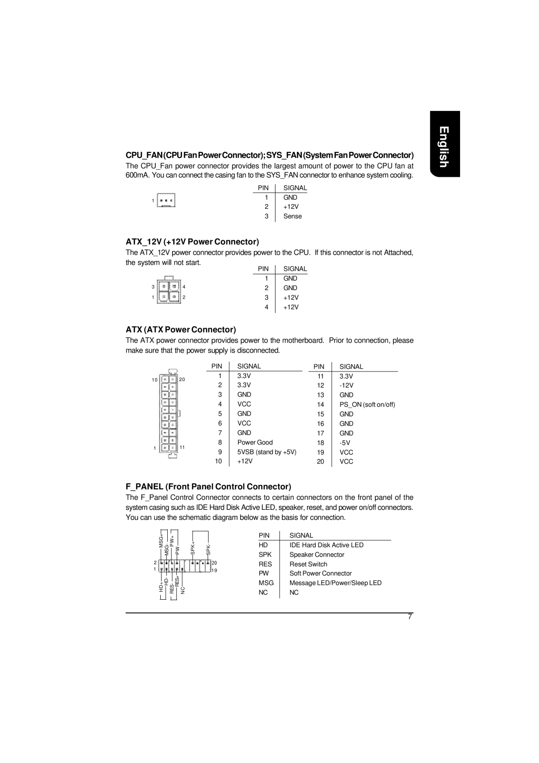
CPU_FAN(CPUFanPowerConnector);SYS_FAN(SystemFanPowerConnector)
The CPU_Fan power connector provides the largest amount of power to the CPU fan at 600mA. You can connect the casing fan to the SYS_FAN connector to enhance system cooling.
| PIN | SIGNAL |
1 | 1 | GND |
|
|
2+12V
3Sense
ATX_12V (+12V Power Connector)
The ATX_12V power connector provides power to the CPU. If this connector is not Attached, the system will not start.
|
| PIN | SIGNAL |
|
| 1 | GND |
3 | 4 | 2 | GND |
1 | 2 | 3 | +12V |
|
| 4 | +12V |
|
|
|
|
ATX (ATX Power Connector)
The ATX power connector provides power to the motherboard. Prior to connection, please make sure that the power supply is disconnected.
|
| PIN | SIGNAL |
| PIN | SIGNAL | |
10 | 20 | 1 | 3.3V | 11 | 3.3V | ||
2 | 3.3V | 12 | |||||
|
| ||||||
|
| 3 | GND | 13 | GND | ||
|
| 4 | VCC | 14 | PS_ON (soft on/off) | ||
|
| 5 | GND | 15 | GND | ||
|
| 6 | VCC | 16 | GND | ||
|
| 7 | GND | 17 | GND | ||
1 | 11 | 8 | Power Good | 18 | |||
9 | 5VSB (stand by +5V) | 19 | VCC | ||||
|
| ||||||
|
| 10 | +12V | 20 | VCC | ||
|
|
|
|
|
|
| |
F_PANEL (Front Panel Control Connector)
The F_Panel Control Connector connects to certain connectors on the front panel of the system casing such as IDE Hard Disk Active LED, speaker, reset, and power on/off connectors. You can use the schematic diagram below as the basis for connection.
|
|
|
|
|
|
|
|
|
|
|
| PIN |
| SIGNAL |
MSG+ | WP + |
|
|
|
|
|
|
| ||||||
SPK+ | HD |
| IDE Hard Disk Active LED | |||||||||||
|
|
|
|
|
|
|
|
|
|
|
|
| ||
2 |
|
|
|
|
|
|
|
|
| 20 | SPK |
| Speaker Connector | |
|
|
|
|
|
|
|
|
| RES |
| Reset Switch | |||
|
|
|
|
|
|
|
| |||||||
1 |
|
|
|
|
| CN | 19 | PW |
| Soft Power Connector | ||||
|
|
|
|
| ||||||||||
HD+ HD- |
|
|
|
| MSG |
| Message LED/Power/Sleep LED | |||||||
|
|
|
|
|
|
|
|
|
|
|
|
| ||
|
|
|
|
|
|
|
|
|
|
|
| NC |
| NC |
English
7