English
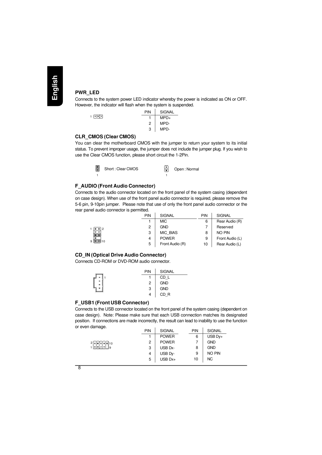
PWR_LED
Connects to the system power LED indicator whereby the power is indicated as ON or OFF. However, the indicator will flash when the system is suspended.
| PIN | SIGNAL |
1 | 1 | MPD+ |
|
2MPD-
3MPD-
CLR_CMOS (Clear CMOS)
You can clear the motherboard CMOS with the jumper to return your system to its initial status. To prevent improper usage, the jumper does not include the jumper plug. If you wish to use the Clear CMOS function, please short circuit the
Short : Clear CMOS | Open : Normal |
1 | 1 |
F_AUDIO (Front Audio Connector)
Connects to the audio connector located on the front panel of the system casing (dependent on case design). When use of the front panel audio connector is required, please remove the
|
| PIN | SIGNAL |
| PIN | SIGNAL | |
|
| 1 | MIC |
| 6 | Rear Audio (R) | |
1 | 2 | 2 | GND | 7 | Reserved | ||
3 | MIC_BIAS | 8 | NO PIN | ||||
|
| ||||||
9 | 10 | 4 | POWER | 9 | Front Audio (L) | ||
5 | Front Audio (R) | 10 | Rear Audio (L) | ||||
|
| ||||||
|
|
|
|
|
|
| |
CD_IN (Optical Drive Audio Connector)
Connects
| PIN | SIGNAL |
1 | 1 | CD_L |
| 2 | GND |
| 3 | GND |
| 4 | CD_R |
|
|
|
F_USB1 (Front USB Connector)
Connects to the USB connector located on the front panel of the system casing (dependent on case design). Note: Please make sure that each USB connection matches its designated position. If connections are made incorrectly, the result can lead to inability to use the function or even damage.
|
| PIN | SIGNAL |
| PIN | SIGNAL |
|
| 1 | POWER | 6 | USB Dy+ | |
2 | 10 | 2 | POWER | 7 | GND | |
1 | 9 | 3 | USB Dx- | 8 | GND | |
|
| 4 | USB Dy- | 9 | NO PIN | |
|
| 5 | USB Dx+ | 10 | NC | |
8