SECTION
MULTI FUNCTION CHARGER PORT
WARNING | FRONT VIEW OF JOYSTICK |
|
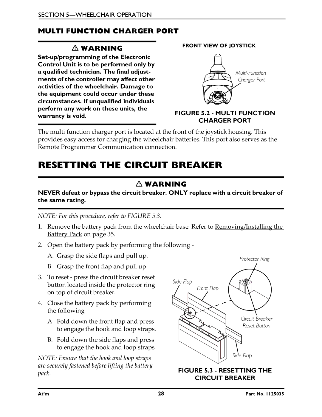
The multi function charger port is located at the front of the joystick housing. This provides easy access for charging the wheelchair batteries. This port also serves as the Remote Programmer Communication connection.
RESETTING THE CIRCUIT BREAKER
WARNING
NEVER defeat or bypass the circuit breaker. ONLY replace with a circuit breaker of the same rating.
NOTE: For this procedure, refer to FIGURE 5.3.
1.Remove the battery pack from the wheelchair base. Refer to Removing/Installing the Battery Pack on page 35.
2.Open the battery pack by performing the following -
A. Grasp the side flaps and pull up. | Protector Ring | |
B. Grasp the front flap and pull up. | ||
| ||
3. To reset - press the circuit breaker reset | Side Flap | |
button located inside the protector ring | ||
Front Flap | ||
on top of circuit breaker. | ||
|
4. Close the battery pack by performing the following -
A.Fold down the front flap and press to engage the hook and loop straps.
B.Fold down the side flaps and press to engage the hook and loop straps.
Circuit Breaker
Reset Button
NOTE: Ensure that the hook and loop straps are securely fastened before lifting the battery pack.
At’m | 28 | Part No. 1125035 |
