| SECTION |
| Exploded View |
POSITIVE (+) | Hex Screw |
RED Cable |
|
| Mounting Plate |
| Clamp |
NEGATIVE | POSITIVE (+) |
BLACK Cable | Terminal/Post |
|
|
|
|
| NEGATIVE |
|
|
| |
|
|
|
|
|
|
|
| ||
|
|
|
|
|
|
|
| ||
|
|
|
|
|
|
|
| ||
Group 22NF Battery |
|
|
|
| Terminal/Post |
|
|
| |
|
|
|
|
|
|
|
| ||
|
|
|
|
|
|
|
| ||
Detail “A” - Top View | Detail “B” - | ||||||||
Fuse box placement when | POSITIVE (+) | NEGATIVE | POSITIVE (+) | ||||||
box top is installed | RED Cable | Terminal/Post | |||||||
Terminal/Post | |||||||||
POSITIVE (+) |
|
|
|
|
| ||||
NEGATIVE |
| RED Clamp | |||||||
Terminal/Post and |
| ||||||||
Terminal/Post and |
| ||||||||
Clamp |
|
|
| Cover | |||||
Clamp |
|
|
| ||||||
|
|
|
|
|
| ||||
NEGATIVE
BLACK Cable
Group 22NF Battery | Group 22NF | ||
Battery | |||
| Fuse Box | ||
| BLACK Clamp | ||
|
| ||
|
| Cover | |
| Detail “C” - Installing Battery Clamp Cover | ||
Clamp |
| Cable | |
|
| ||
Cover |
|
| |
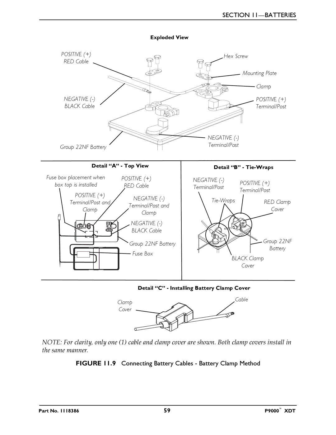
NOTE: For clarity, only one (1) cable and clamp cover are shown. Both clamp covers install in the same manner.
FIGURE 11.9 Connecting Battery Cables - Battery Clamp Method
Part No. 1118386 | 59 | P9000™ XDT |