CV-A11
10. Appendix
10.1. CV-A11 emulating CV-M10 interfacing
The
Please note: Only a qualified electronics technician or engineer should make these changes.
Hirose pin # | Function | JP2 | JP3 | JP5 | JP1 | JP4 | Remarks |
9 | PCLK output enabled | Short |
|
|
|
| Note 2 |
9 | No connection | Open |
|
|
|
|
|
10 | WEN output |
| Open | Short |
|
|
|
10 | Connected to ground |
| Short | Open |
|
|
|
11 | Ext Trigger input |
|
|
| Open | Short |
|
11 | +12V DC in |
|
|
| Short | Open |
|
Note 1: Configuration shown in Bold+Italic is factory default setting
Note 2: The
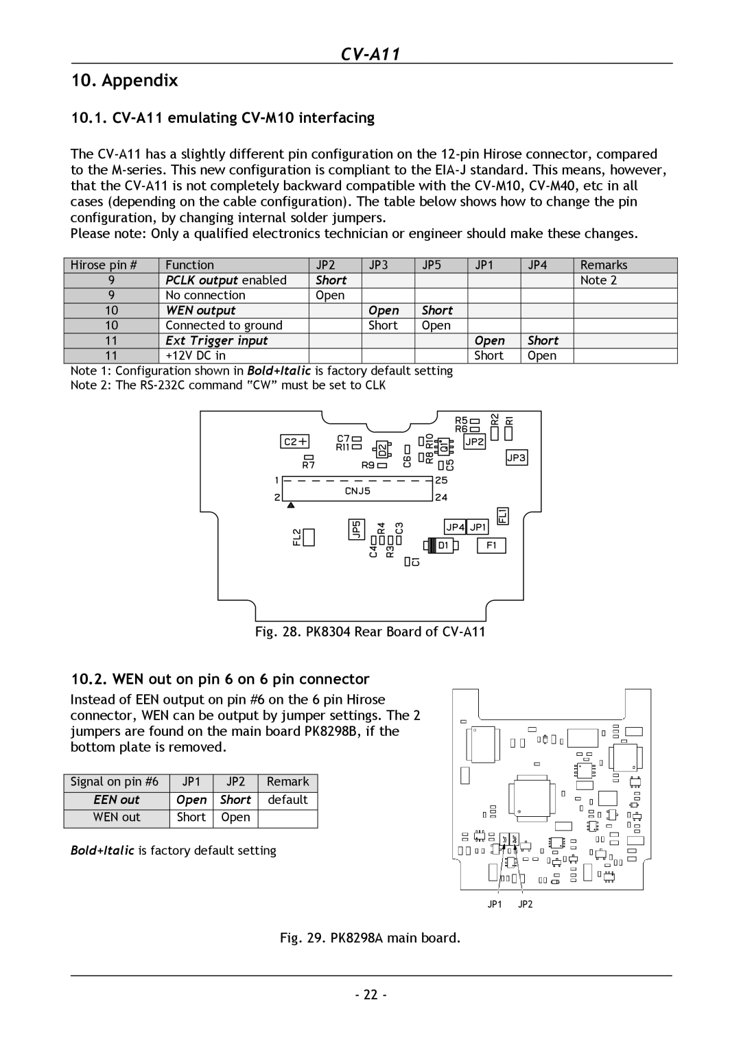
Fig. 28. PK8304 Rear Board of CV-A11
10.2. WEN out on pin 6 on 6 pin connector
Instead of EEN output on pin #6 on the 6 pin Hirose connector, WEN can be output by jumper settings. The 2 jumpers are found on the main board PK8298B, if the bottom plate is removed.
Signal on pin #6 | JP1 | JP2 | Remark |
EEN out | Open | Short | default |
WEN out | Short | Open |
|
Bold+Italic is factory default setting
JP1 JP2
Fig. 29. PK8298A main board.
- 22 -