CV-L105
5.4. Input and Output Circuits
Video outputs, timing outputs, trigger input and control inputs are found on the 68 pin LVDS connector.
5.4.1. Video output
The digital
Red channel video output |
|
+RD0 to +RD7 | Bits 0 to 7 positive side of the differential signal |
Bits 0 to 7 negative side of the differential signal | |
Green channel video output | |
+GD0 to +GD7 | Bits 0 to 7 positive side of the differential signal |
Bits 0 to 7 negative side of the differential signal | |
Blue channel video output +BD0 to +BD7
Bit 0 is LSB. Bit 7 is MSB.
STROBE
LEN
Bits 0 to 7 positive side of the differential signal
Bits 0 to 7 negative side of the differential signal
This signal is used to latch the digital video into the frame grabber.
Line enable, this signal is high during the
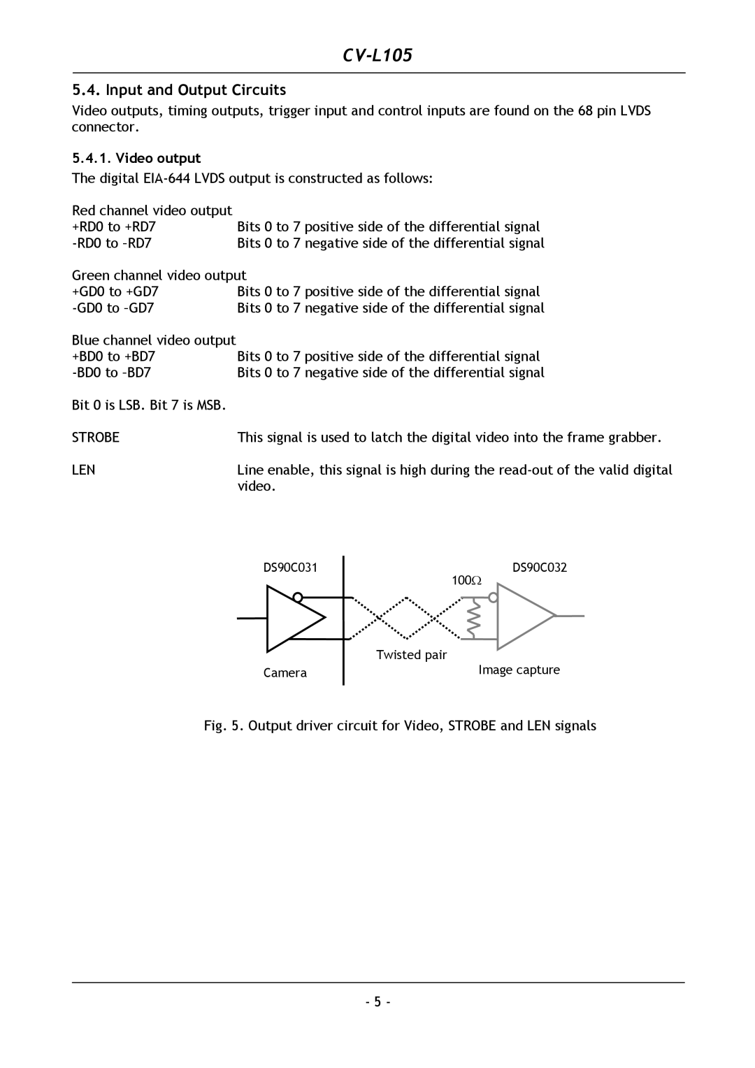
DS90C031 | DS90C032 |
| 100Ω |
| Twisted pair |
Camera | Image capture |
Fig. 5. Output driver circuit for Video, STROBE and LEN signals
- 5 -