CV-L105
5.2. 6-pin Hirose connector (Power)
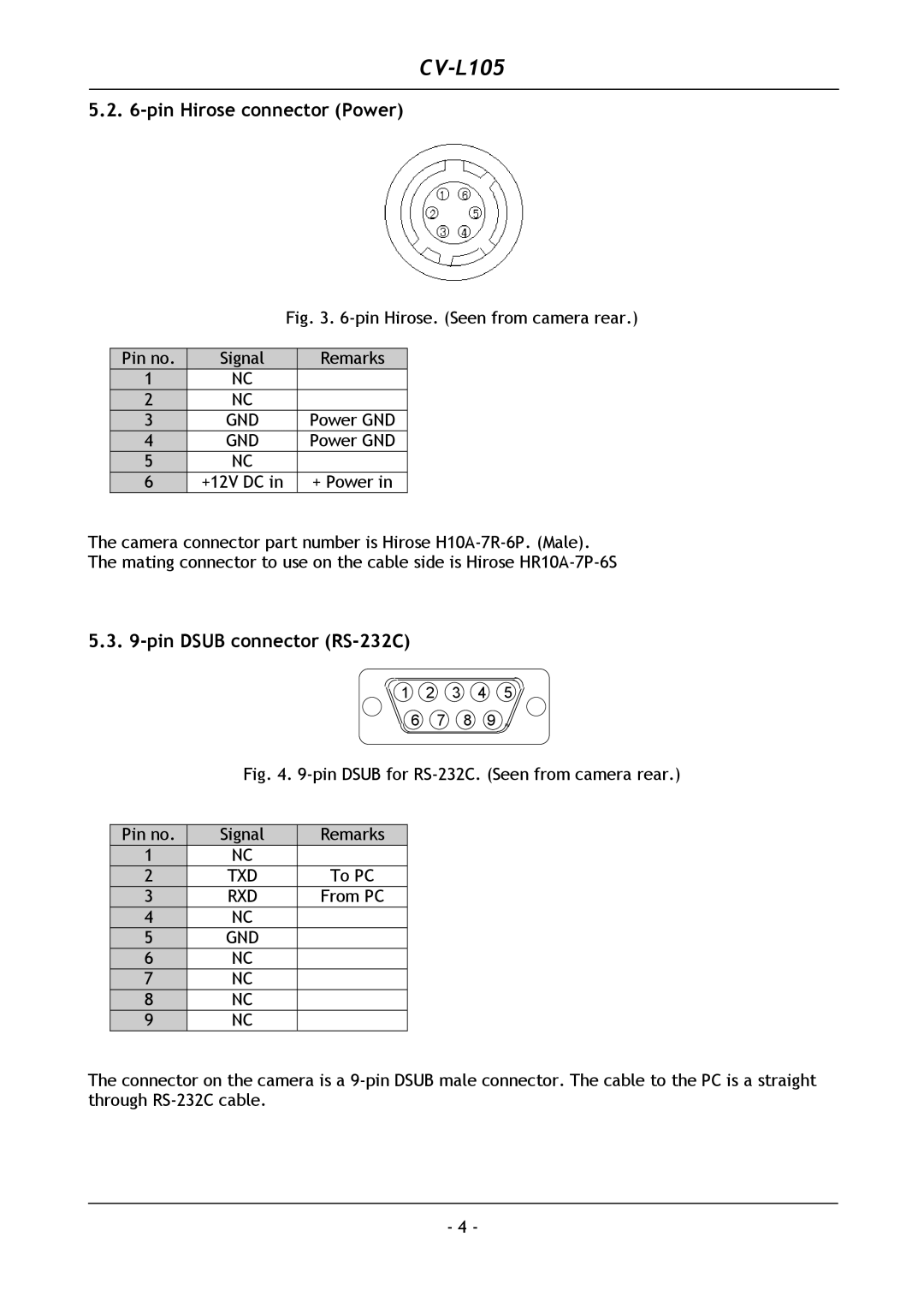
Fig. 3. 6-pin Hirose. (Seen from camera rear.)
Pin no. | Signal | Remarks |
1 | NC |
|
2 | NC |
|
3 | GND | Power GND |
4 | GND | Power GND |
5 | NC |
|
6 | +12V DC in | + Power in |
The camera connector part number is Hirose
5.3. 9-pin DSUB connector (RS-232C)
1 2 3 4
6 7 8
5
6
Fig. 4. 9-pin DSUB for RS-232C. (Seen from camera rear.)
Pin no. | Signal | Remarks |
1 | NC |
|
2 | TXD | To PC |
3 | RXD | From PC |
4 | NC |
|
5 | GND |
|
6 | NC |
|
7 | NC |
|
8 | NC |
|
9 | NC |
|
The connector on the camera is a
- 4 -
