Connector Wiring
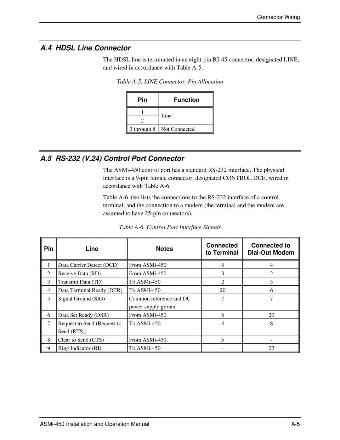
A.4 HDSL Line Connector
The HDSL line is terminated in an
Table
Pin
Function
1 | Line | |
2 | ||
| ||
3 through 8 | Not Connected |
A.5 RS-232 (V.24) Control Port Connector
The
Table
Table
Pin | Line | Notes | Connected | Connected to | |
to Terminal |
| ||||
|
|
| |||
|
|
|
|
| |
|
|
|
|
| |
1 | Data Carrier Detect (DCD) | From | 8 | 4 | |
2 | Receive Data (RD) | From | 3 | 2 | |
3 | Transmit Data (TD) | To | 2 | 3 | |
4 | Data Terminal Ready (DTR) | To | 20 | 6 | |
5 | Signal Ground (SIG) | Common reference and DC | 7 | 7 | |
|
| power supply ground |
|
| |
6 | Data Set Ready (DSR) | From | 6 | 20 | |
7 | Request to Send (Request to | To | 4 | 8 | |
| Send (RTS)) |
|
|
| |
8 | Clear to Send (CTS) | From | 5 | - | |
9 | Ring Indicator (RI) | To | - | 22 | |
|
|
|
|
|