Trace Oxygen Analyzer | Installation 3 | |
|
|
|
|
|
|
|
|
|
3.3Electrical Connections
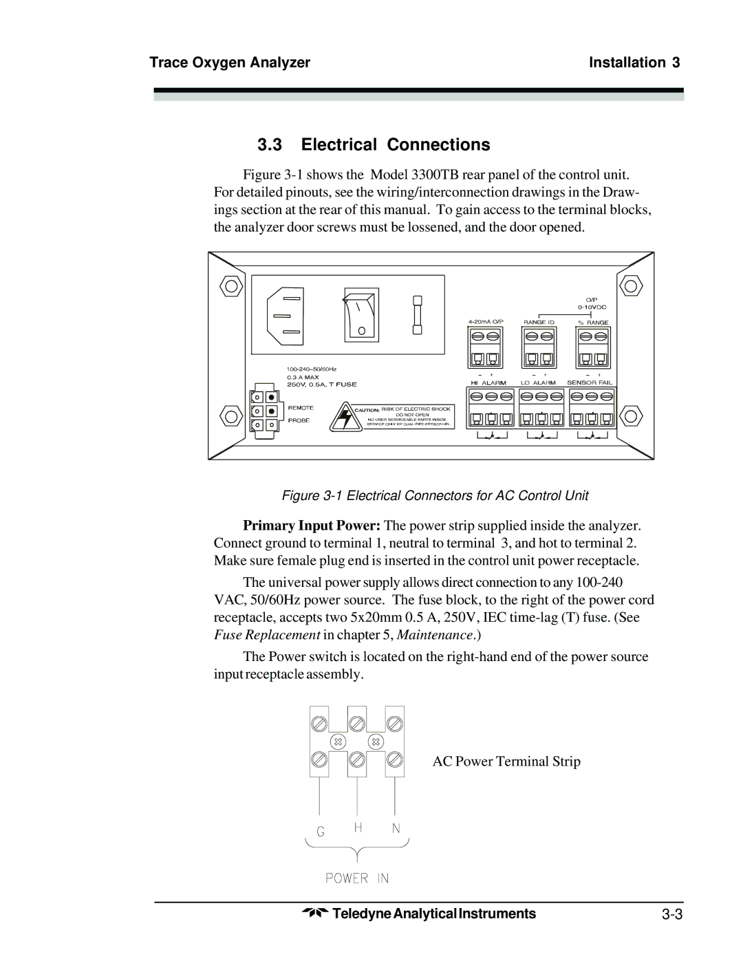
Figure 3-1 shows the Model 3300TB rear panel of the control unit. For detailed pinouts, see the wiring/interconnection drawings in the Draw- ings section at the rear of this manual. To gain access to the terminal blocks, the analyzer door screws must be lossened, and the door opened.
Figure 3-1 Electrical Connectors for AC Control Unit
Primary Input Power: The power strip supplied inside the analyzer. Connect ground to terminal 1, neutral to terminal 3, and hot to terminal 2. Make sure female plug end is inserted in the control unit power receptacle.
The universal power supply allows direct connection to any
The Power switch is located on the
AC Power Terminal Strip
Teledyne Analytical Instruments |