3 Installation | Model 3300TB | |
|
|
|
|
|
|
|
|
|
3.2Location and Mounting
3.2.1 Control Unit Installation
The 3300TB Control Unit is designed to be
Refer to the Outline diagram
3.2.2 Installing the Micro-Fuel Cell / Cell Block Orientation
A
Also, once it is expended, or if the instrument has been idle for a lengthy period, the
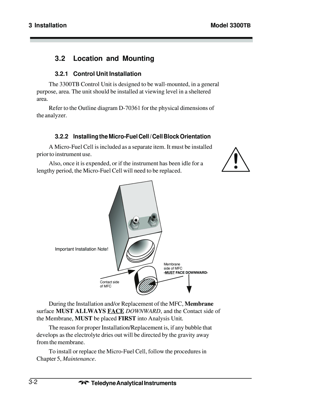
Important Installation Note!
Membrane side of MFC
Contact side of MFC
During the Installation and/or Replacement of the MFC, Membrane surface MUST ALLWAYS FACE DOWNWARD, and the Contact side of the Membrane, MUST be placed FIRST into Analysis Unit.
The reason for proper Installation/Replacement is, if any bubble that develops as the electrolyte dries out will be directed by the gravity away from the membrane.
To install or replace the
Teledyne Analytical Instruments |