Trace Oxygen Analyzer | Operational Theory 2 | |
|
|
|
|
|
|
|
|
|
2.3Electronics
2.3.1 General
The signal processing uses an Intel microcontroller with
The power supply circuitry is on the Power Supply PCB, which is mounted vertically, just behind the rear panel of the Control Unit.
The signal processing electronics including the sensor amplifier, microcontroller, analog to digital, and digital to analog converters are located on the Main PCB, which is mounted vertically, just behind the front panel of the Control Unit.
2.3.2 Signal Processing
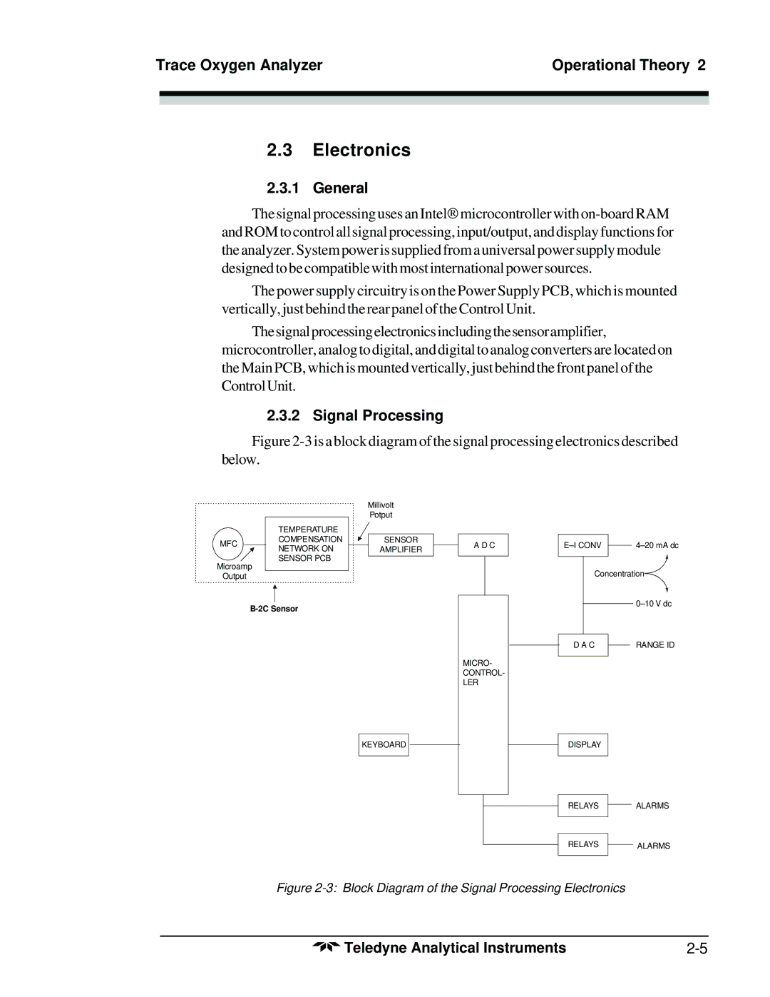
Figure 2-3 is a block diagram of the signal processing electronics described below.
MFC
TEMPERATURE COMPENSATION NETWORK ON SENSOR PCB
Millivolt
Potput
SENSOR AMPLIFIER
A D C
| ||
| ||
|
|
|
Microamp
Output
MICRO- CONTROL- LER
Concentration![]()
| D A C |
| RANGE ID |
|
| ||
|
|
|
|
KEYBOARD
DISPLAY
RELAYS
ALARMS
RELAYS
ALARMS
Figure 2-3: Block Diagram of the Signal Processing Electronics
Teledyne Analytical Instruments |